How ev charger works?
How ev charger works?
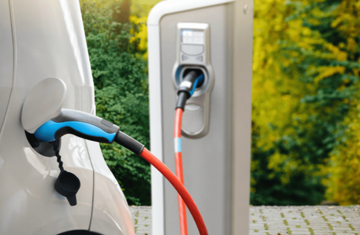
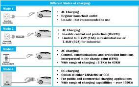
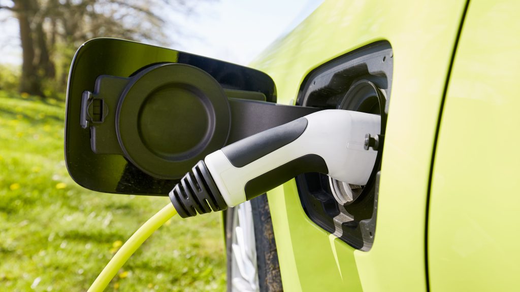
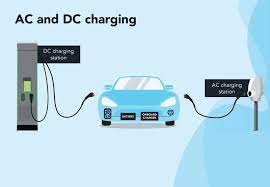
Electric vehicle (EV) chargers operate through two fundamental methods: DC fast charging and AC slow charging, with the core difference lying in where the electrical conversion happens and the resulting charging speed. Understanding these two modes reveals the fascinating interplay of power electronics, communication systems, and battery management that safely fuels modern EVs.
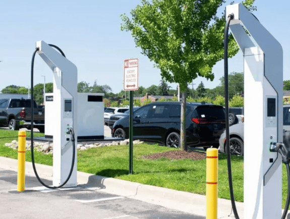
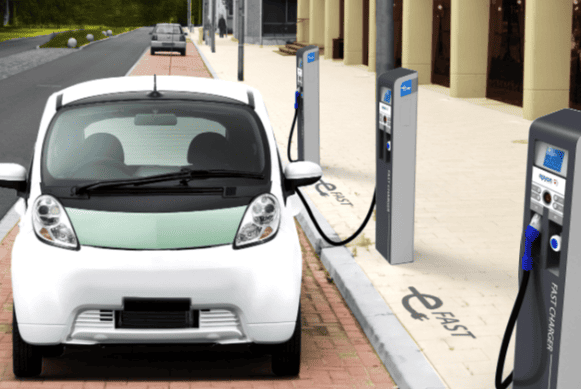
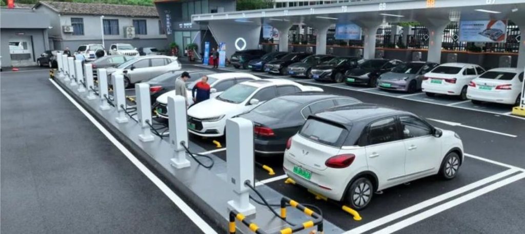
I. DC Fast Charging (Off-Board Conversion)
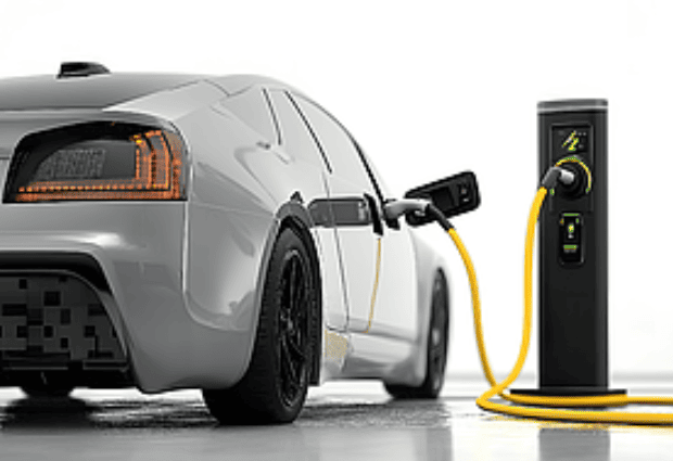
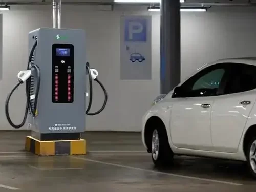
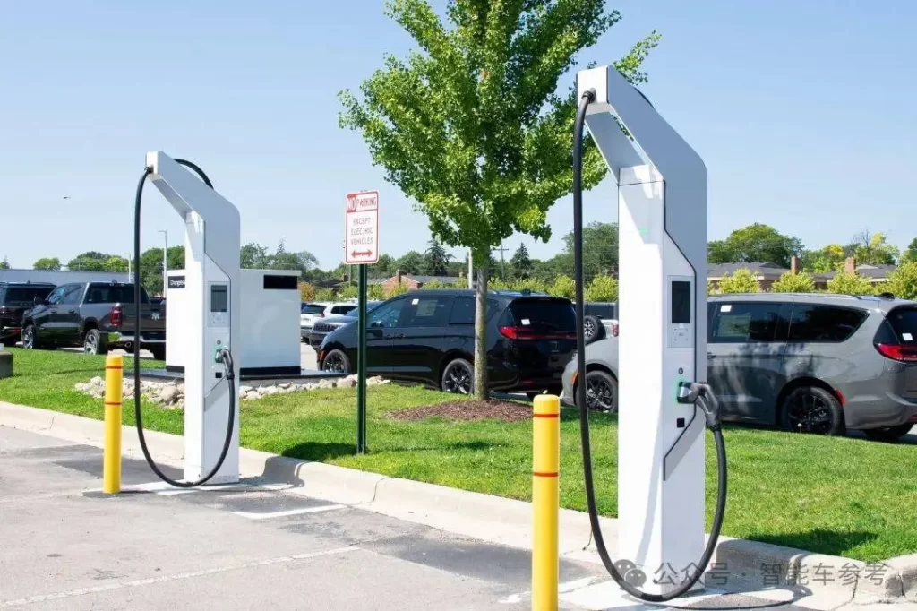
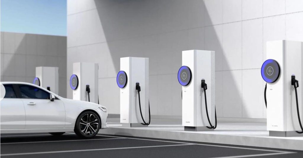
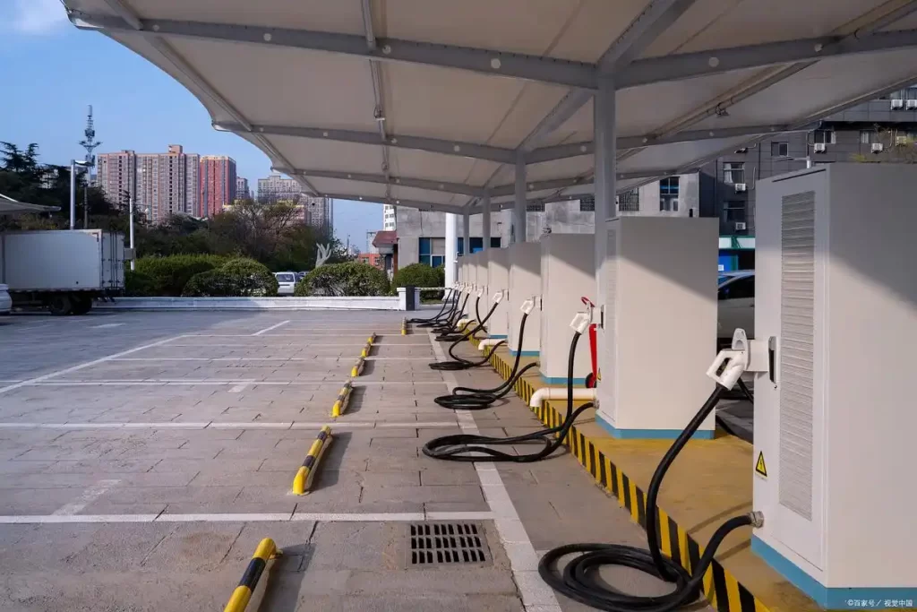
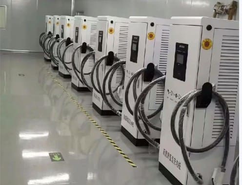
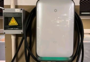
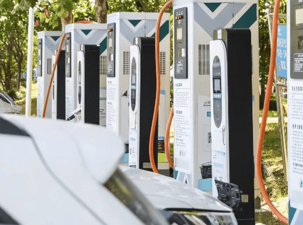
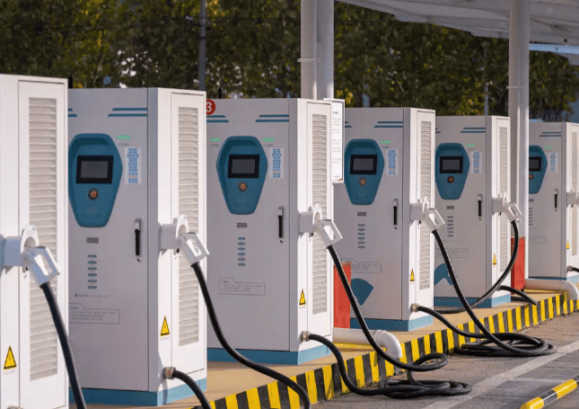
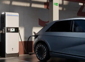
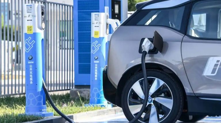
DC fast charging, often found at public stations and highway rest stops, delivers a powerful jolt of energy by handling the critical AC-to-DC conversion outside the vehicle. This externalization of power conversion allows for significantly higher power levels and dramatically reduced charging times. Here’s how it works step-by-step:
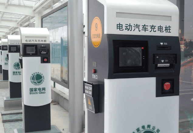
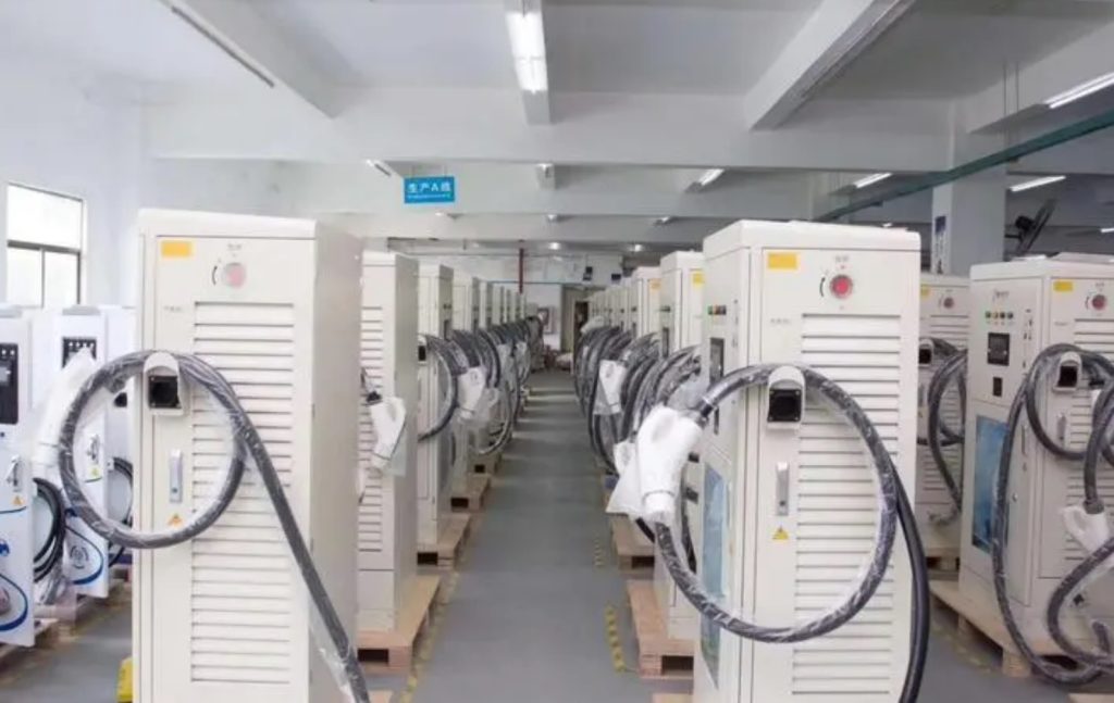
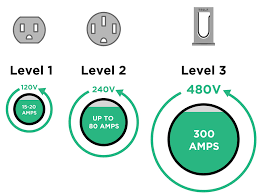
- Direct High-Voltage Conversion: A high-capacity electrical supply, usually a 380V (or higher) three-phase AC industrial grid connection, is directly connected to the charging station, also known as a DC fast charger or just a “fast charger.” Strong rectifier modules do the heavy lifting inside the charger’s sturdy cabinet. These advanced electronic circuits transform incoming AC power into extremely high-voltage DC, usually between 200 and 750 volts, or even 1000 volts in the most recent ultra-fast systems. For pushing significant amounts of power—typically between 60 kW and 180 kW, though more recent chargers can reach 350 kW or more—directly into the EV’s battery pack, this high-voltage DC is essential.Alongside the rectifiers, a dedicated control unit manages the entire process, while insulation monitoring circuits constantly check for any potential electrical leakage to ground, ensuring fundamental safety before any power flows.
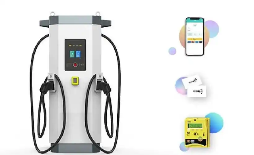
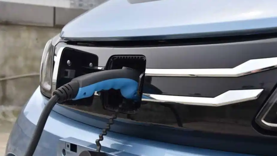
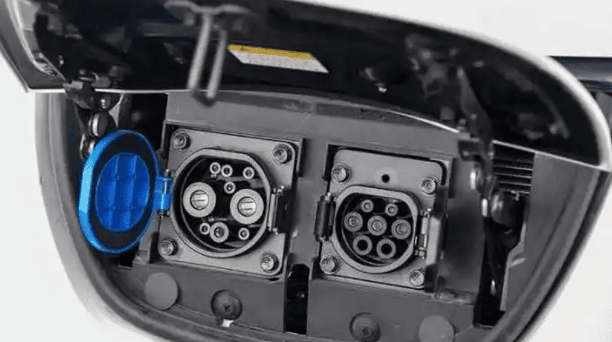
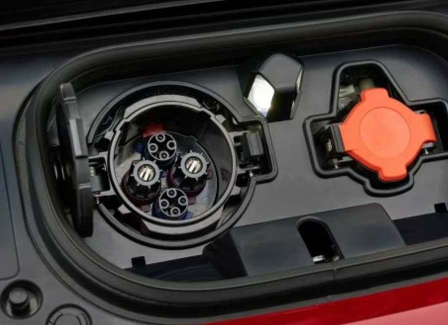
- Precision Communication & Control: Without continuous, accurate communication, simply pumping high-voltage DC into a battery would be risky. The CHAdeMO/GB/T connector, also known as the Combined Charging System (CCS) connector, is essential in this situation. The connector’s dedicated communication pins, which are frequently designated S+ and S-, create a constant digital data connection between the charger and the car’s Battery Management System (BMS). Consider the BMS to be the guardian and brain of the battery. It continuously tracks vital parameters like voltage, temperature, and state of charge while keeping an eye on each individual cell inside the enormous battery pack. The BMS actively interacts with the charger during fast charging. Based on cell conditions and temperature, it informs the charger of the battery’s current voltage as well as the maximum charging current permitted at that specific time. The charger then dynamically adjusts its output to match these limits exactly. This real-time negotiation prevents catastrophic events like overcharging (which can cause fires) or overheating (thermal runaway). As the battery approaches around 80% capacity, the BMS instructs the charger to significantly reduce the current, switching to a gentle “trickle charge” or “taper” mode. This protects the battery chemistry from stress at high states of charge.
- Multi-Layered Safety Fortress: Strong safety engineering is required when handling hundreds of kilowatts. Advanced thermal control is essential. The battery produces a lot of heat while fast charging. The car’s liquid cooling system, which is the most popular kind for battery packs, goes into overdrive. In order to actively maintain the optimal operating temperature range, which is typically between 25°C and 40°C, coolant is pumped through channels surrounding the battery modules, absorbing heat and transferring it to a radiator. The development of lithium dendrites, which are tiny metallic needles that can develop inside batteries during incorrect charging and possibly pierce internal separators, resulting in short circuits and fires, is severely inhibited by this exact temperature control, which is not just about efficiency. Additionally, the car and the charger both have advanced electrical safety features.These include ground fault detection, robust isolation monitoring to ensure no dangerous voltage reaches the car’s chassis, and voltage surge protection. Crucially, fast chargers have internal residual charge discharge circuits. When charging stops or is disconnected, these circuits safely drain any leftover high-voltage electricity stored within the charger’s capacitors within milliseconds, preventing dangerous sparks or shocks when the connector is unplugged.
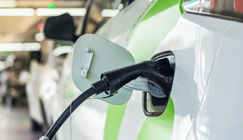
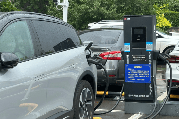
II. AC Slow Charging (On-Board Conversion)
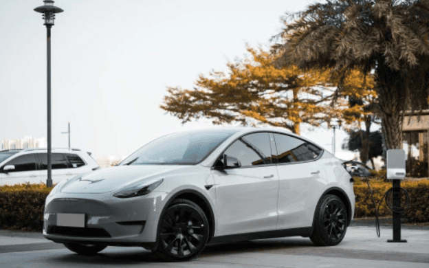
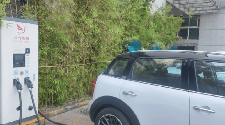
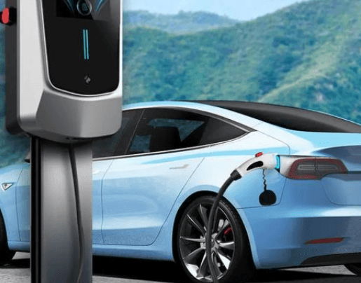
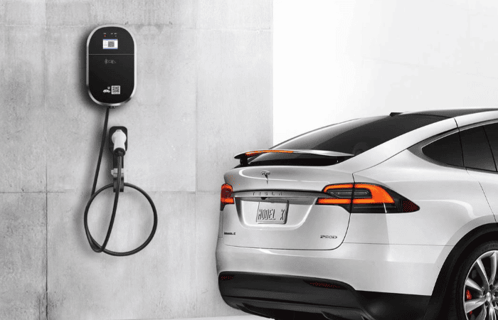
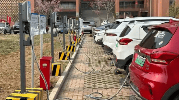
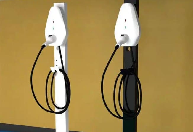
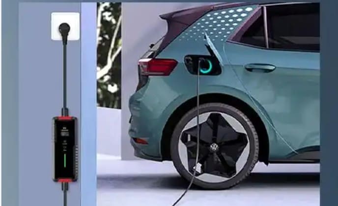
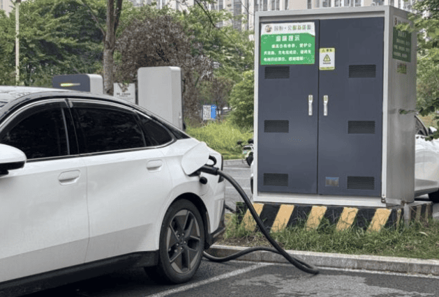
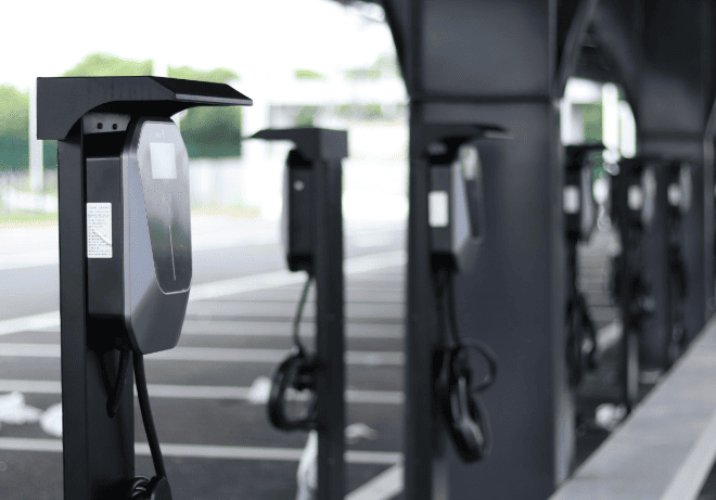
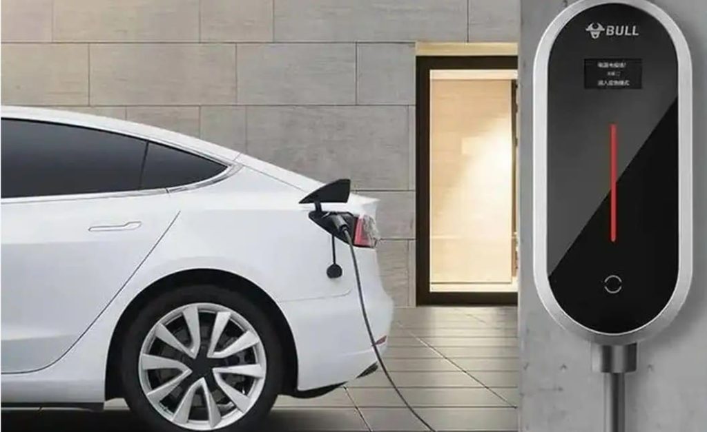
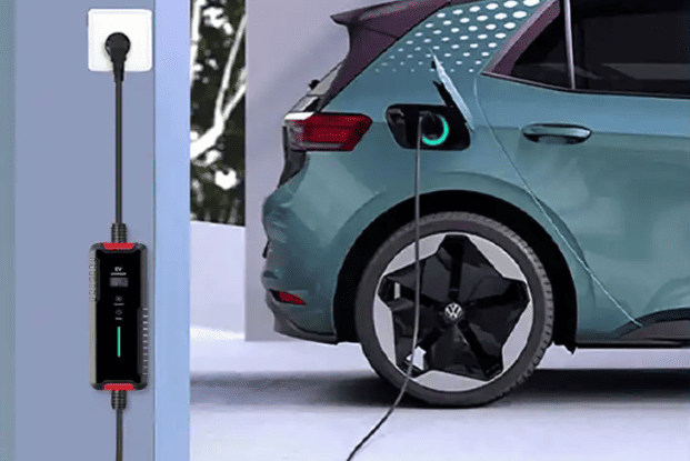
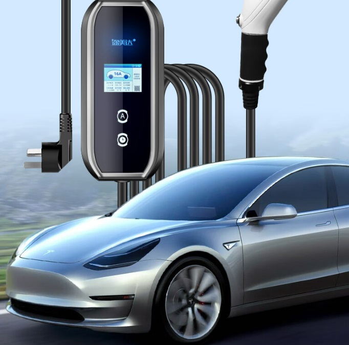
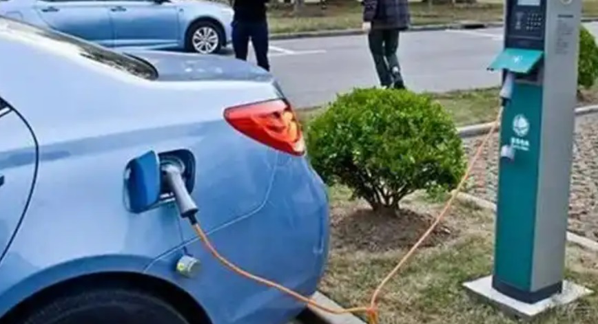
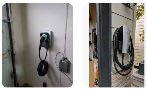
AC slow charging, the most common method for home and workplace charging, utilizes the existing AC power grid (like a standard household outlet or a slightly more powerful dedicated circuit) but relies on the vehicle itself to convert this AC power into the DC power the battery needs.
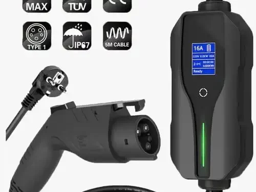
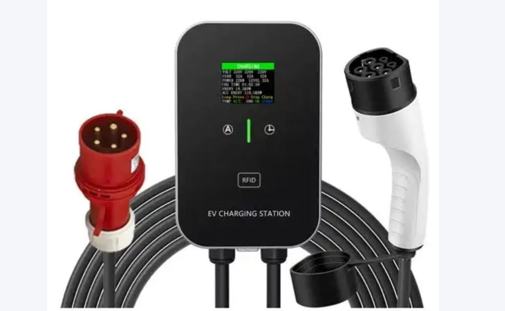
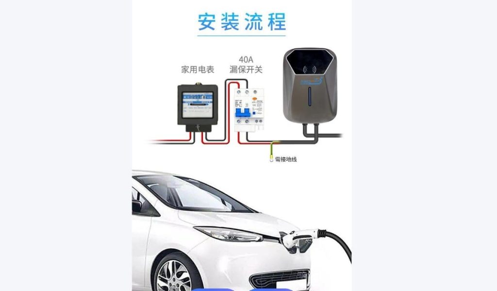
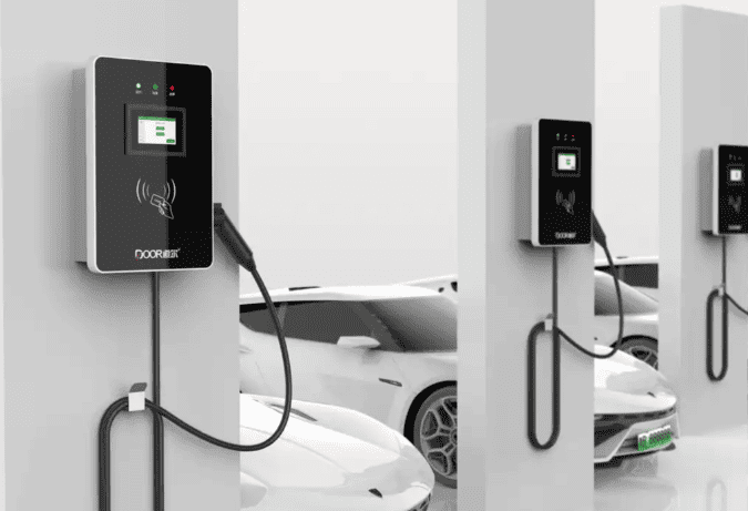
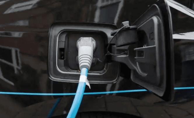
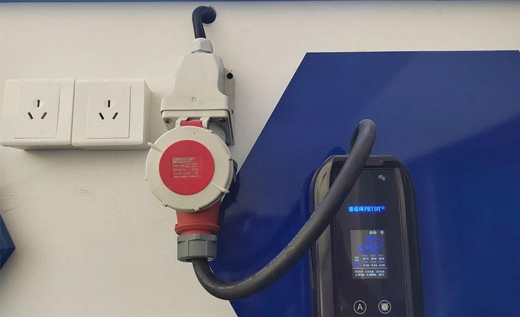
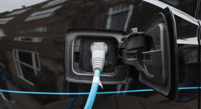
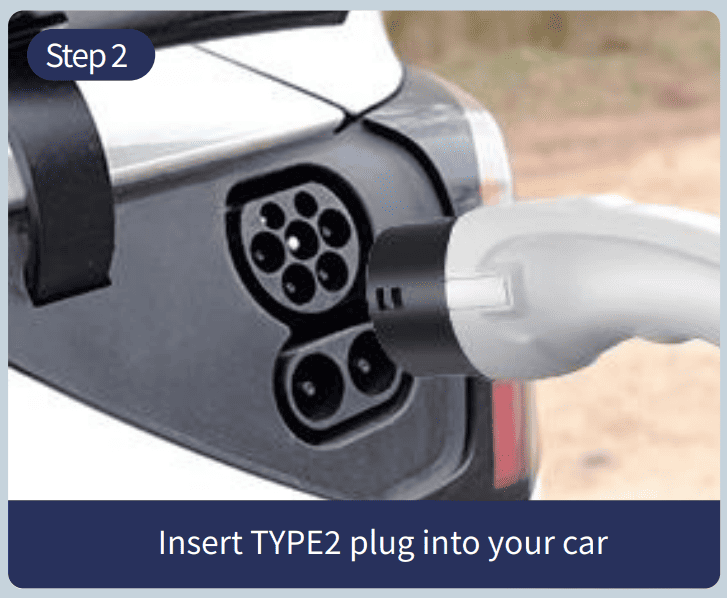
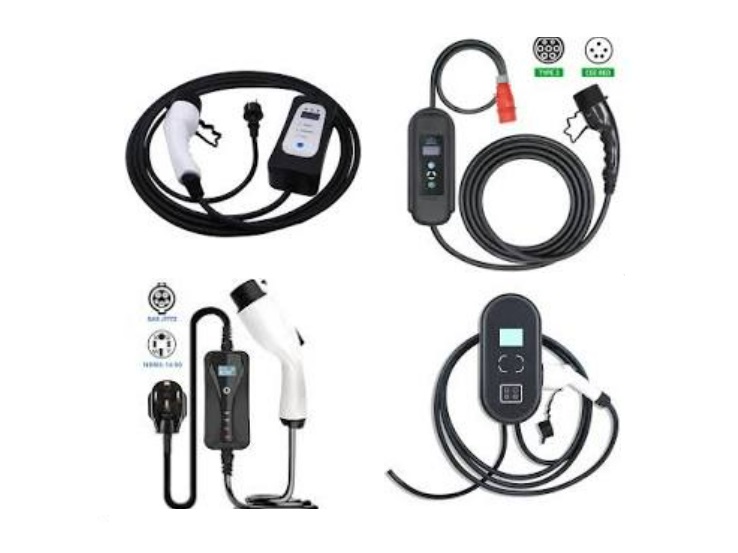
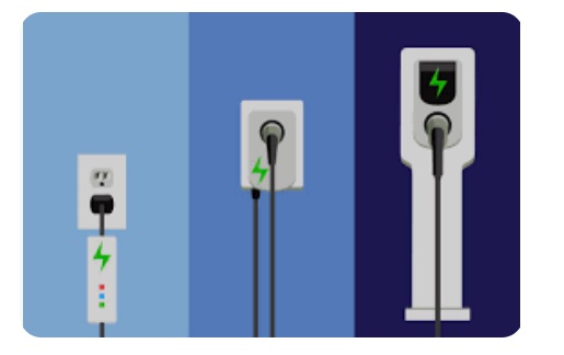
- On-Board Power Conversion: An AC charging cable connects your EV directly to the standard AC power grid. For basic home charging, this cable is usually 220V (or 120V in North America) single-phase AC, but for faster “Wallbox” units for homes or offices, it can occasionally be 380V three-phase AC. The On-Board Charger (OBC) is a component that performs the crucial conversion work inside the car. In essence, the OBC is a small, integrated power supply. It rectifies (converts AC to DC) the incoming AC power after changing its voltage level. Additionally, it adjusts this DC output to precisely match the battery pack’s required voltage and current profile. Due to size, weight, and cost constraints within the vehicle, OBCs are significantly less powerful than external DC fast chargers. Typical power ratings range from about 3.3 kW (a standard 220V/16A outlet) up to 11 kW or occasionally 22 kW for vehicles equipped with high-power three-phase OBCs. Consequently, charging times are much longer – often requiring 5 to 10 hours or even overnight for a full charge from empty.
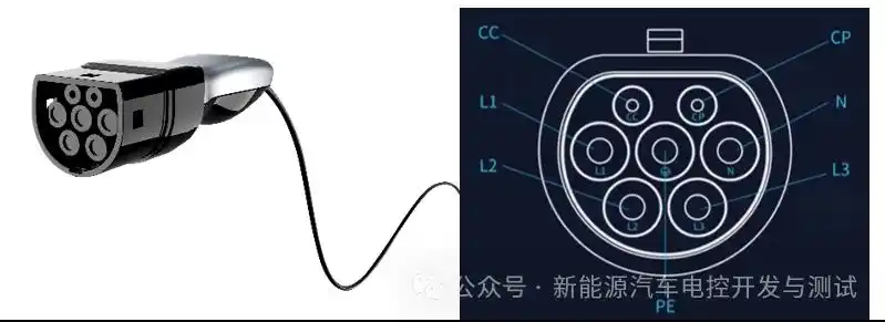
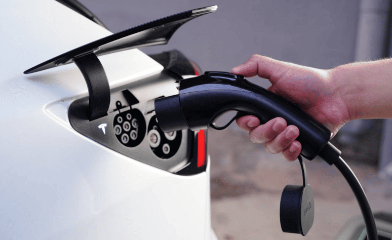
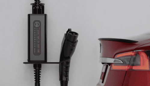
- The Connection Handshake: Before any AC power flows, a careful electronic “handshake” occurs between the vehicle and the charging station (even a simple home EVSE – Electric Vehicle Supply Equipment) to ensure everything is connected correctly and safely. When the charging connector is plugged into the car’s inlet, specific pins (usually called Control Pilot (CP) and Proximity Pilot (PP) or sometimes Connection Confirm (CC)) initiate communication. The EVSE sends a small pilot signal. The car detects this signal and responds by applying specific resistances across these pins. This resistance-based signaling creates predictable voltage drops that the EVSE measures. By interpreting these voltage levels, the EVSE confirms a secure physical connection and, crucially, identifies the maximum current capacity of the cable itself (preventing overload). Simultaneously, the EVSE and the vehicle’s OBC communicate using a Pulse Width Modulation (PWM) signal on the control pilot line. The duty cycle (on/off timing) of this PWM signal encodes information about the EVSE’s available power. The OBC receives this, compares it to the battery’s needs (as dictated by the BMS), and signals back what power level it will draw. Only after this full negotiation is complete does the EVSE close its internal contactors, allowing full AC power to flow to the OBC.
- The Long-Term Battery Benefit: While slow, AC charging offers significant advantages for long-term battery health. The lower charging currents (compared to DC fast charging) significantly reduce the polarization effect within the battery cells. Polarization refers to the build-up of chemical byproducts or concentration gradients at the electrodes during charging, which can increase internal resistance and stress the battery over time. Slower charging minimizes this, leading to less chemical degradation. Furthermore, AC charging is perfectly suited for overnight charging during off-peak electricity hours (often called “valley” periods), significantly reducing charging costs for the owner. This combination of gentle charging and cost-effective timing makes regular AC slow charging the recommended primary method for maximizing the overall lifespan and health of an EV’s expensive battery pack.
III. The Symphony of Supporting Systems
The smooth and safe operation of both charging modes relies on the flawless integration of several critical vehicle systems working in concert:
- The Brain: Battery Management System (BMS): The BMS is the undisputed master controller during any charging event. It continuously monitors the voltage, temperature, and sometimes even pressure of every single cell or group of cells (module) within the high-voltage battery pack. Using a dedicated communication network (typically the Controller Area Network or CAN bus), it constantly exchanges vital data with both the OBC (during AC charging) and the external DC fast charger. The BMS calculates and dictates the absolute maximum safe charging current and voltage limits in real-time based on the battery’s instantaneous condition and temperature. It enforces these limits rigorously, overriding charger requests if necessary to prevent overcharging, over-temperature, or cell imbalance. Its algorithms manage the crucial transition to trickle charging as the battery fills up.
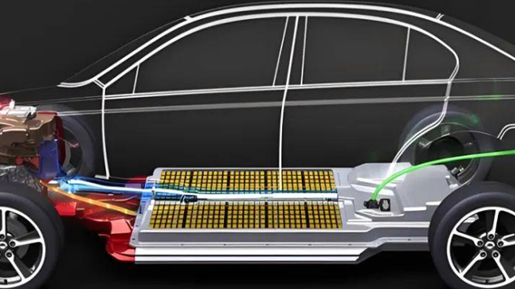
- The Climate Control: Thermal Management System: Batteries operate best within a specific temperature window. Charging, especially fast DC charging, generates substantial heat. Conversely, charging in very cold conditions is inefficient and can be damaging. The vehicle’s thermal management system is essential for maintaining this optimal temperature range. During charging, it actively circulates coolant (in liquid-cooled systems) or air (in air-cooled systems) around the battery pack. For fast charging, it aggressively removes heat. In cold weather, it may actually pre-heat the battery using grid power or waste heat from other systems before allowing significant charging current to flow, ensuring efficiency and safety. This precise thermal control directly impacts charging speed, safety, and long-term battery health.
- The Safety Shield: Electrical Isolation & Protection: Handling hundreds of volts requires multiple layers of electrical safety. The entire high-voltage circuit – including the battery pack, power electronics (OBC, inverter, DC/DC converter), and charging ports – is rigorously isolated from the vehicle’s low-voltage (12V) system and the metal chassis. This prevents any dangerous high voltage from reaching the user or causing shorts. Both the external charging station and the vehicle incorporate sophisticated safety mechanisms: Ground Fault Circuit Interrupters (GFCIs) or Residual Current Devices (RCDs) instantly cut power if they detect even a tiny leakage current flowing to ground (indicating a potential shock hazard). Over-Current Protection (OCP) and Over-Voltage Protection (OVP) circuits guard against electrical surges or faults. Isolation Monitoring Devices (IMDs) continuously check the integrity of the high-voltage system’s isolation from the chassis. Redundant systems ensure that if one safety measure fails, another will activate.
IV. Optimizing Your Charging Strategy
Choosing the right charging method depends on your needs and circumstances:
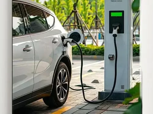
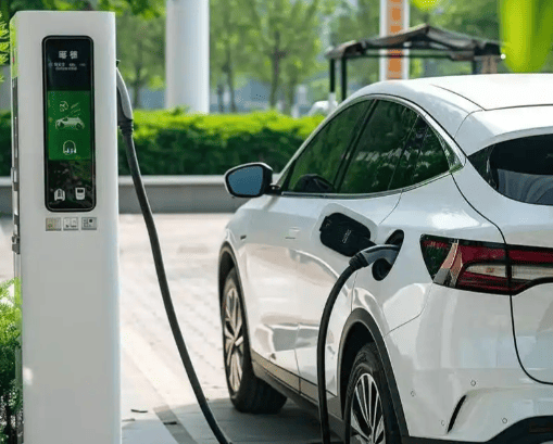
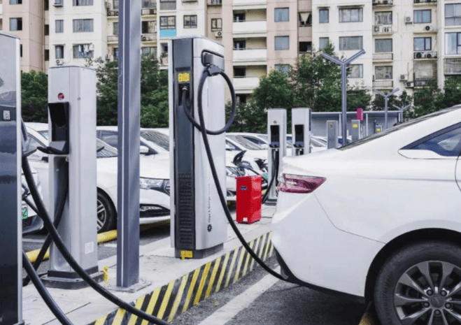
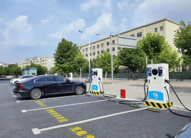
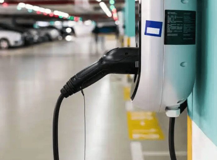
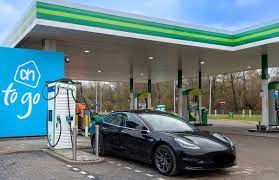
- DC Fast Charging (DCFC) is ideal for long-distance travel, urgent top-ups, or when time is critical. Its major advantage is speed – replenishing 50% to 80% of the battery capacity in often 20 to 40 minutes. However, this speed comes at a cost. The very high currents and associated heat generation place significant stress on the battery chemistry. Frequent and repeated use of DCFC, especially to very high states of charge (like 100%), can accelerate the long-term degradation of the battery, reducing its overall capacity and lifespan faster than slower charging methods. It’s also generally more expensive per kilowatt-hour than home charging.
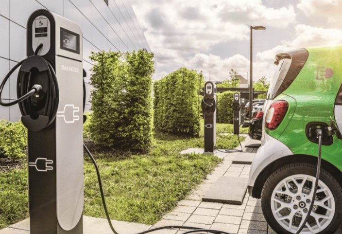
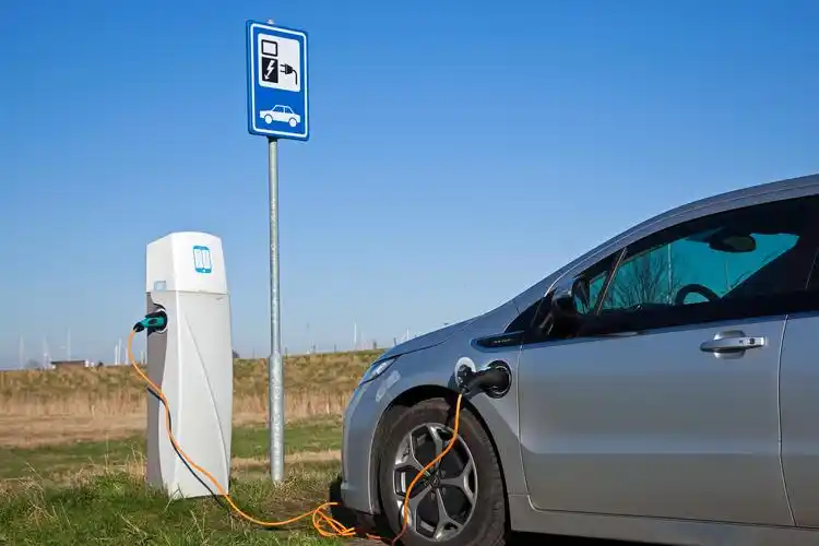
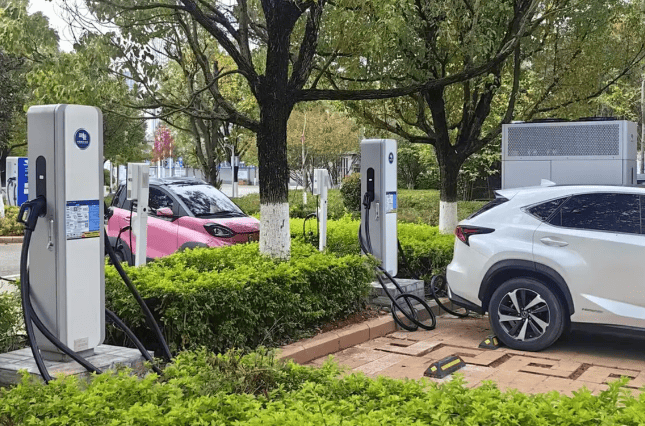
- AC Slow Charging is the cornerstone of daily EV ownership, particularly for home charging overnight. Its primary benefits are battery longevity – the gentle currents minimize chemical stress and polarization – and significantly lower cost, especially if scheduled during off-peak utility rate periods. The main drawback is the time commitment, requiring several hours for a substantial recharge. Planning charging sessions around your vehicle’s downtime (like overnight) easily mitigates this. For most daily driving needs, charging overnight at home provides ample range.
Beyond the Plug: Regenerative Braking
It’s worth noting that charging isn’t solely about plugging in. EVs harness regenerative braking, a process where the electric motor acts as a generator during deceleration or braking. This converts the vehicle’s kinetic energy back into electrical energy, feeding it directly into the battery pack. While not a primary charging method, regenerative braking significantly recaptures energy that would otherwise be lost as heat in traditional friction brakes, enhancing overall driving efficiency and extending the vehicle’s practical range between plug-in charges.
The Heart of It All: The EV Charger Defined
At its core, an Electric Vehicle Charger is a specialized power conversion device designed to safely and efficiently transfer electrical energy from the grid into an EV’s high-voltage battery pack. As we’ve explored, they come in two fundamental types:
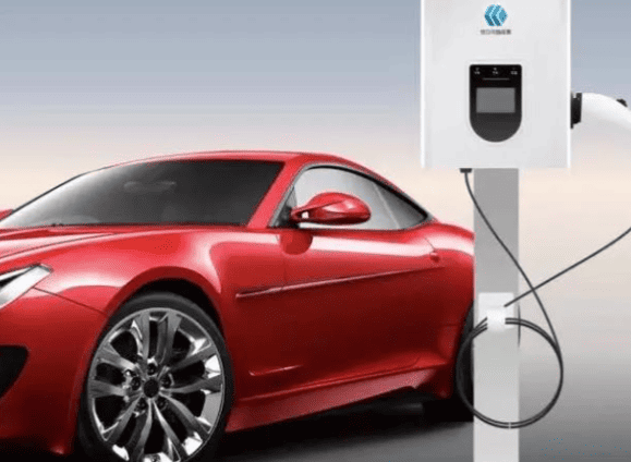
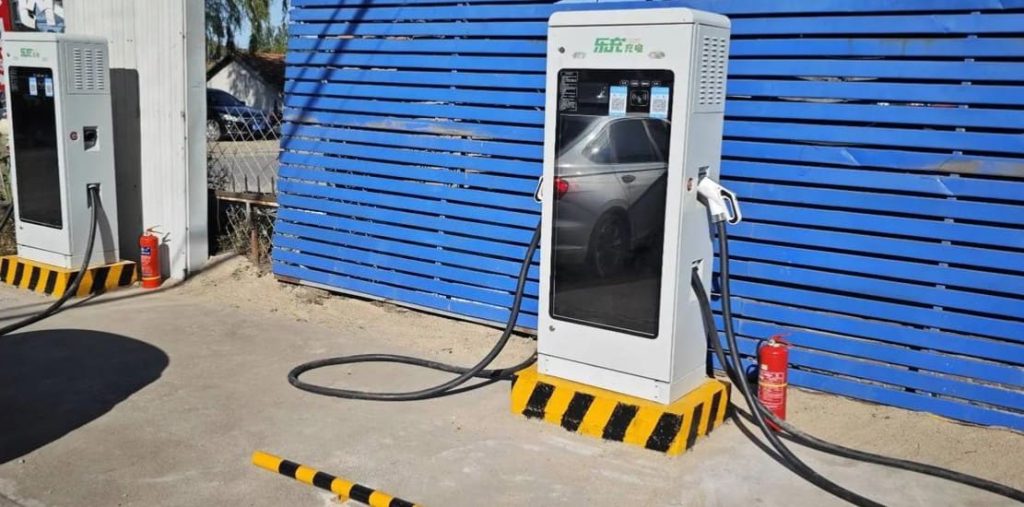
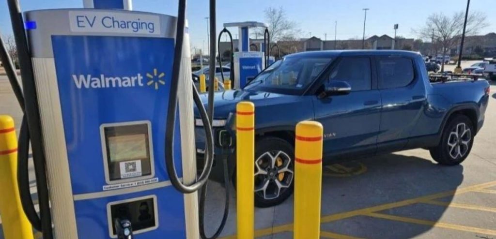
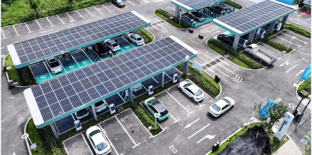
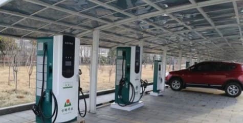
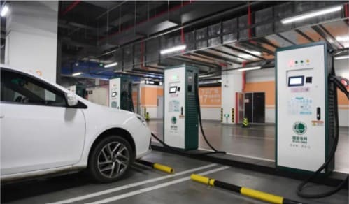
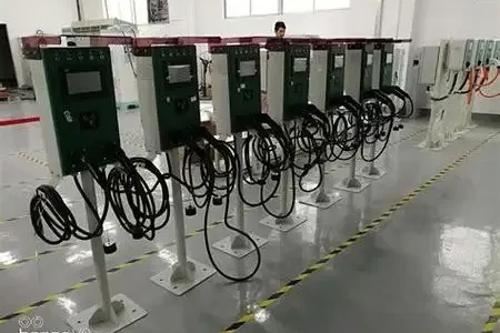
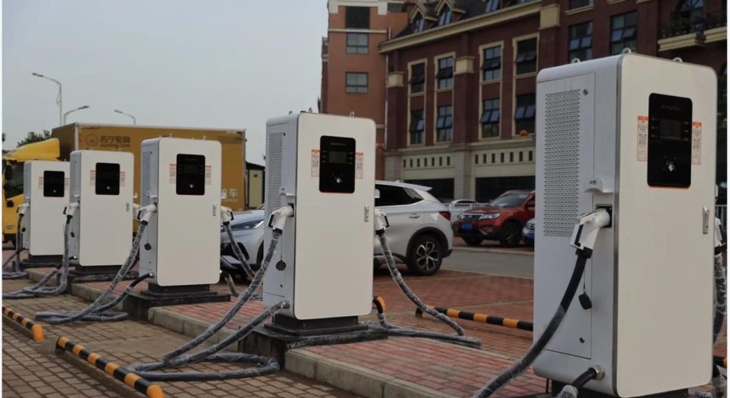
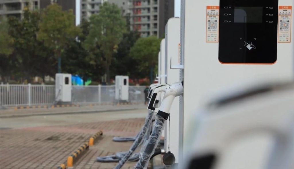
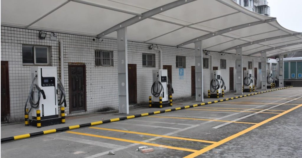
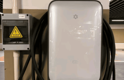
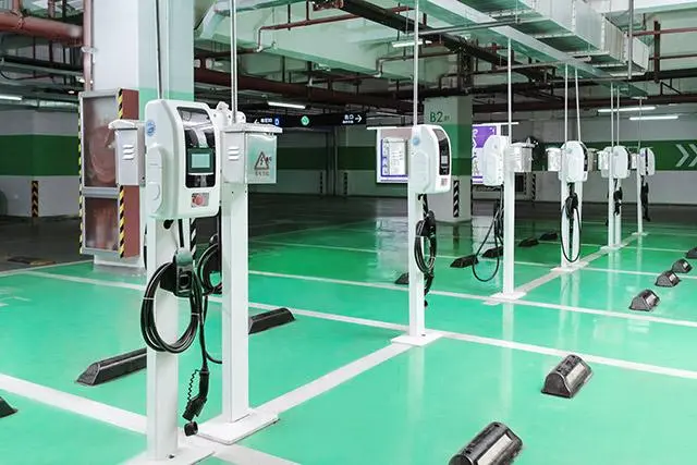
- DC Chargers (Fast Chargers): These powerful external units convert grid AC directly into high-voltage DC, delivering it straight to the battery for rapid replenishment. They are complex, expensive pieces of infrastructure found in public locations.
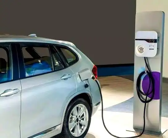
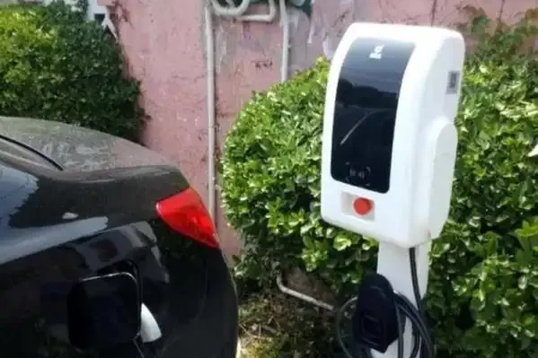
- AC Chargers (On-Board Chargers – OBC): This component is built into the vehicle itself. It receives AC power from the grid (via an external EVSE which primarily acts as a smart switch and safety device) and performs the AC-to-DC conversion internally at lower, gentler power levels suitable for extended charging periods.
Modern chargers are highly sophisticated. They employ Buck-Boost converter topologies to efficiently regulate voltage and current across a wide range of battery states. They support various control modes (automatic via BMS, manual overrides, safety bypasses) and feature clear status indicators. Chargers are designed for high efficiency (typically over 90%), meaning minimal energy is lost as heat during the conversion process. Robust protection circuits are integral, guarding against overloads, short circuits, over-temperature, and electrical faults. Chargers are categorized by their power level (high-power DC vs. lower-power AC), their operating frequency (traditional larger/heavier line-frequency units using transformers vs. modern smaller/lighter high-frequency units using advanced power electronics), and their input specifications (meeting national standards like 380V ±10% three-phase AC for DC chargers or 220V ±10% single-phase AC for common AC EVSEs).
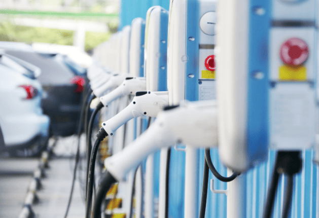
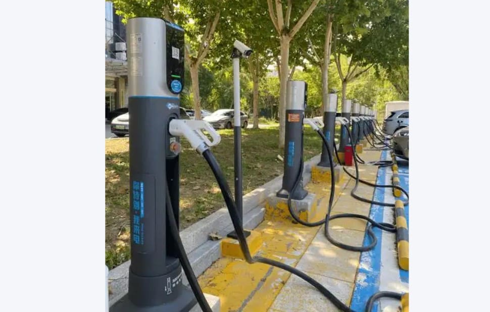
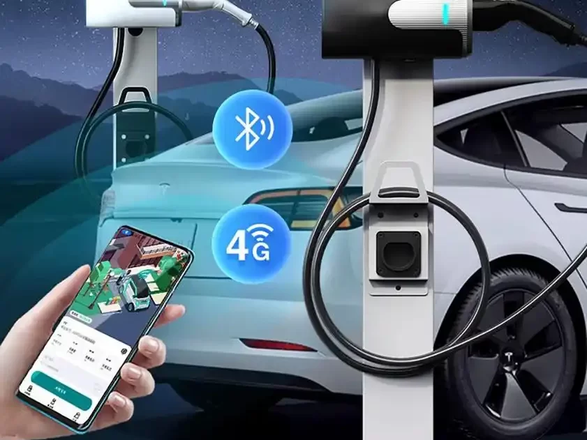
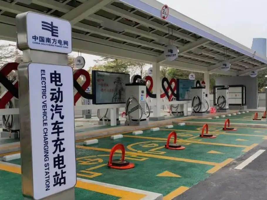
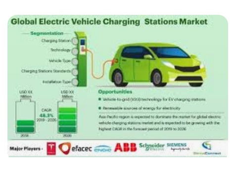
The EV charging landscape is changing quickly. Compatibility is being improved by connector standardization (such as CCS and GB/T becoming more prevalent). Globally, governments and utilities are making significant investments in the expansion of charging infrastructure; for example, China’s State Grid plans to have more than 4,000 charging stations by 2025. The emergence of smart charging networks enables improved user services, integration with renewable energy sources, and optimized grid load management. These developments are essential to EV ownership becoming as popular and convenient as traditional automobiles. One gains a greater understanding of the technology driving the electric revolution by comprehending how the charger itself functions—that complex dance of power conversion, communication, and thermal management.
Contact Us
Contact Us
Contact Us
Whatsapp/Mobile: +86 13641968560
Email: sales@lkmixer.com