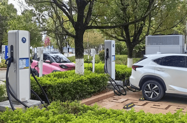
How does ev charging work?

How does ev charging work? Through careful voltage control and component communication, electric vehicle charging transforms alternating current (AC) from the power grid into direct current (DC) stored in the battery. Grid connection, power conversion, battery management, and safety control are the four crucial steps in this process, and there are notable technical differences between international markets. We break down each layer of this electro-mechanical symphony below.
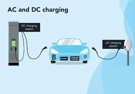
Core Principle: AC to DC Transformation
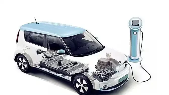
Every EV charging session solves a fundamental problem: grids deliver oscillating AC power, but batteries store energy as stable DC electricity. This conversion happens either:
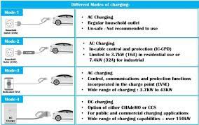
- Inside the vehicle via the On-Board Charger (OBC) during slow AC charging
- At the charging station via external rectifiers during fast DC charging
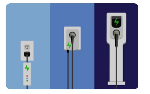
The path differs by charging speed:
- Slow Charging (AC): Grid AC → Vehicle’s OBC → DC → Battery
- Fast Charging (DC): Grid AC → Station Rectifier → DC → Battery
Lithium-ion batteries require precisely controlled DC voltage (typically 350-800V). Deviations risk damage—which is why communication systems between components are as vital as the energy flow itself.
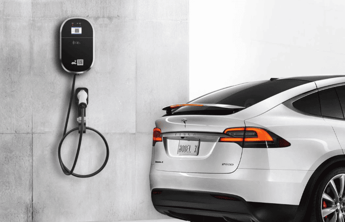
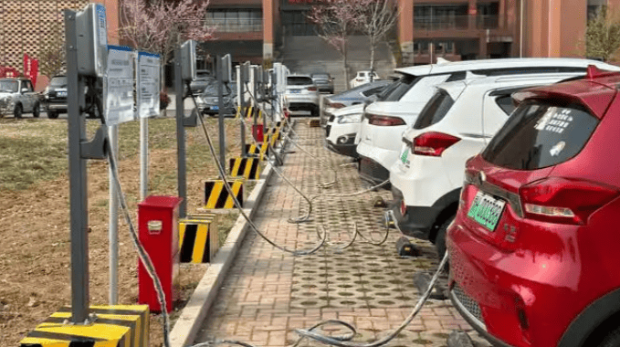
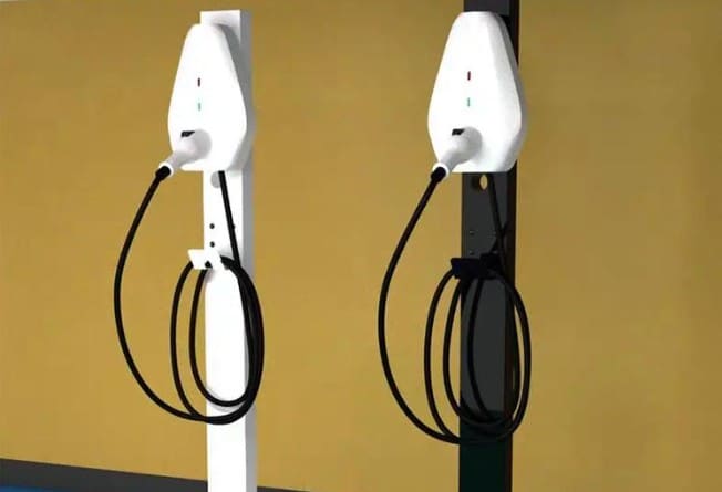
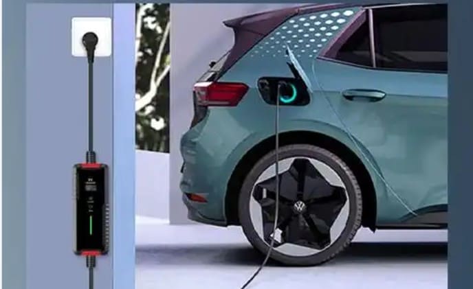
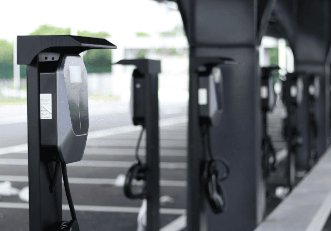
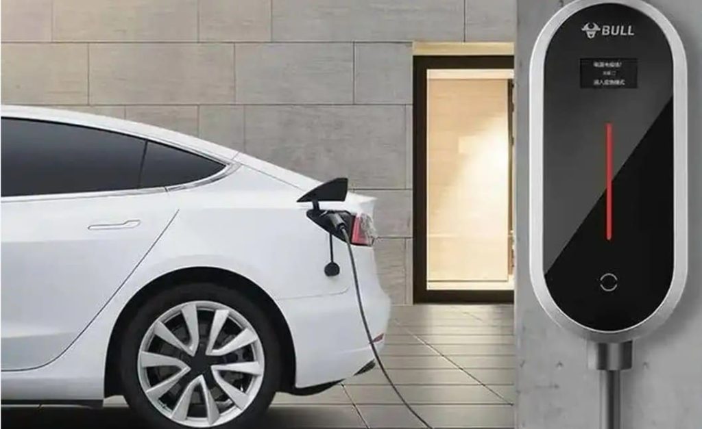
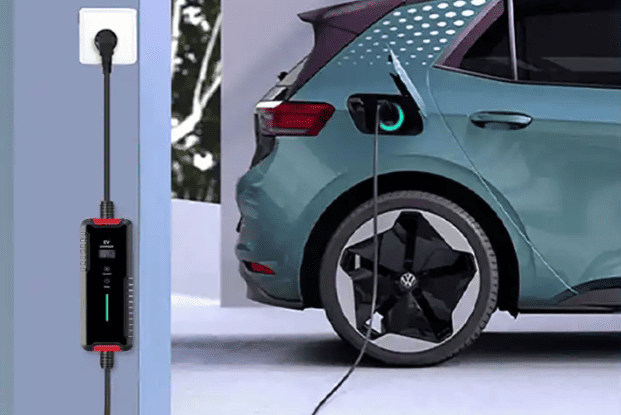
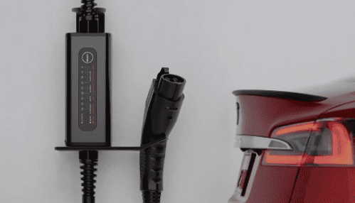
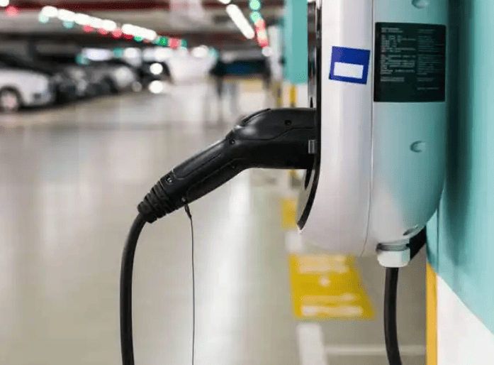
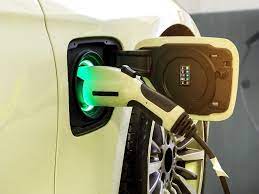
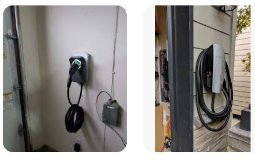
Slow Charging (AC) Mechanics: The On-Board Charger’s Role
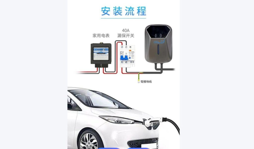
Used for home/workplace charging (6-10 hours), AC charging relies on the vehicle’s built-in power converter:
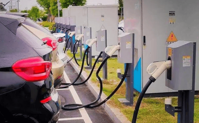
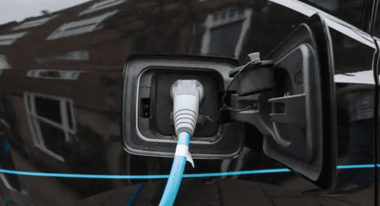
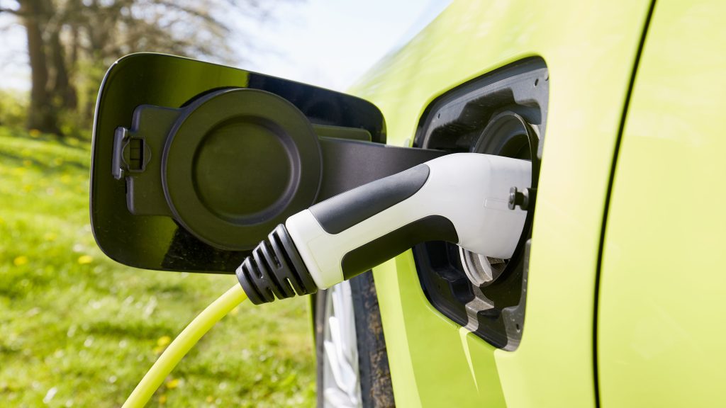
Step 1: Grid Connection & Handshake
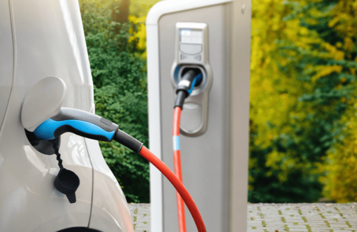
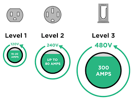
When you plug into a Level 2 charger (EU: 230V/400V; US: 240V):
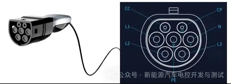
- The charging cable’s control pilot pin sends a PWM signal to the car’s Battery Management System (BMS).
- The BMS replies with battery status (temperature, state of charge).
- The charger adjusts output to match the vehicle’s maximum AC acceptance (e.g., 11 kW for EU models, 19.2 kW for premium US EVs).
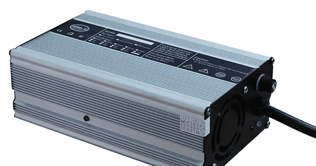
Step 2: AC-to-DC Conversion Inside the Vehicle
The On-Board Charger (OBC)—a shoebox-sized unit under the rear seat—performs critical tasks:
- Rectification: Converts incoming AC to rough DC using diodes or MOSFETs.
- Power Factor Correction (PFC): Aligns current/voltage waveforms to prevent grid harmonics (required by EU IEC 61000-3-2 standards).
- DC-DC Conversion: Fine-tunes voltage to the battery’s needs (e.g., 400V for Hyundai Kona, 800V for Porsche Taycan).
Example: A European Renault Zöe’s 22 kW OBC can add 120 km of range per hour.
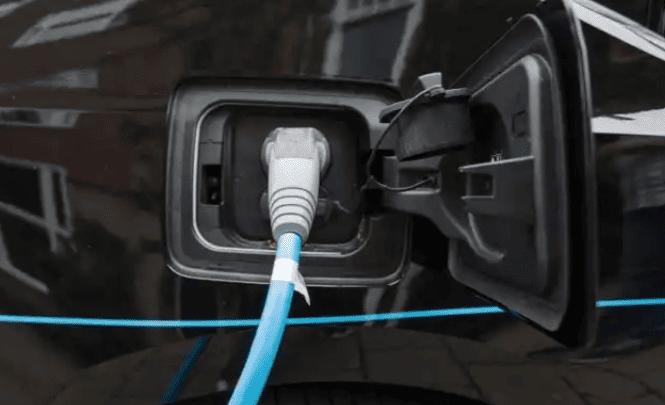
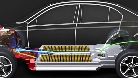
Step 3: Battery Storage & Monitoring
Converted DC flows to the battery via high-voltage cables. The BMS continuously:
- Balances cell voltages (±0.01V tolerance)
- Limits charge rate if temperatures exceed 45°C
- Stops charging at 100% SOC (state of charge) to prevent lithium plating
Manufacturer Insight: OBCs are weight-optimized (3-8 kg) and 94-97% efficient. Tesla integrates them with drive units for packaging efficiency.
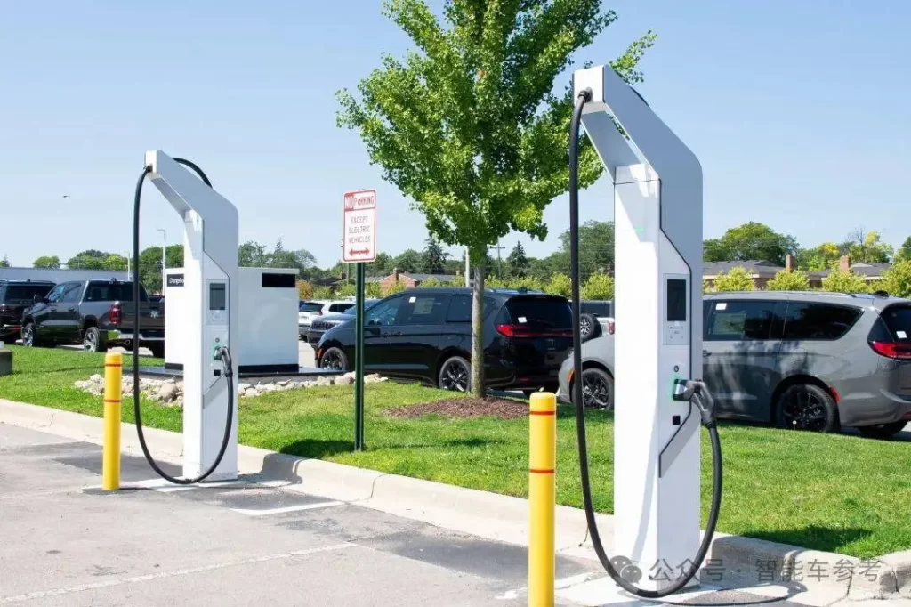
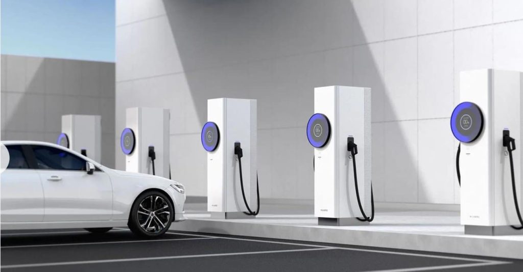
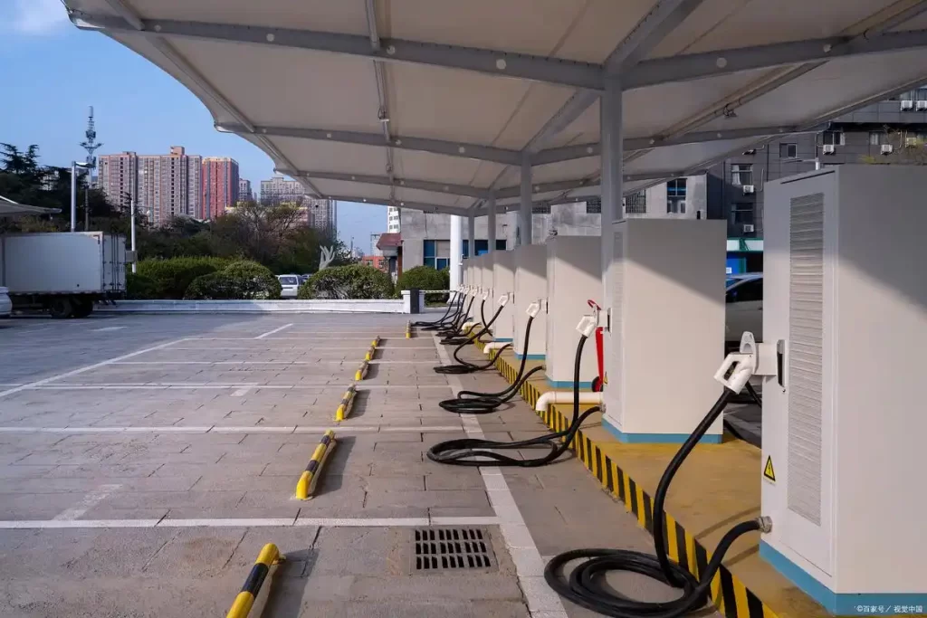
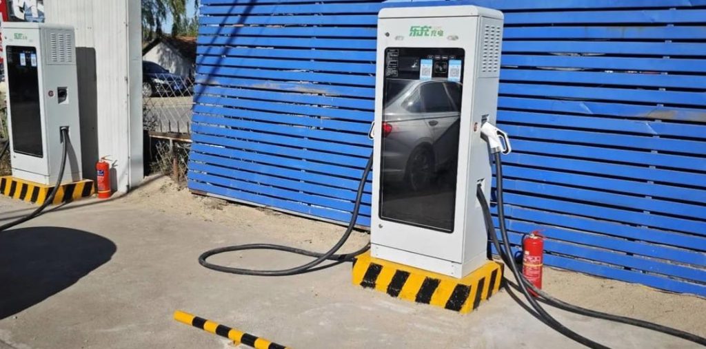
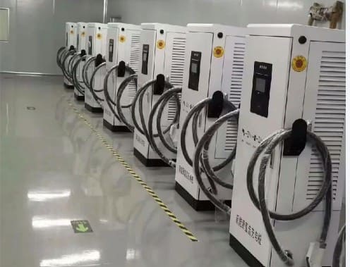
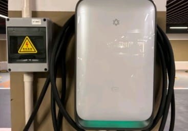
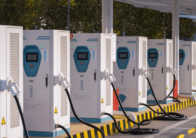
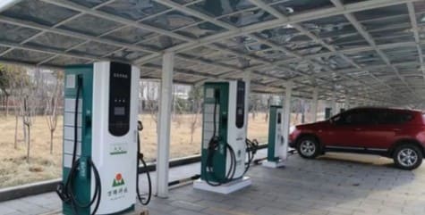
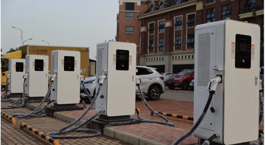
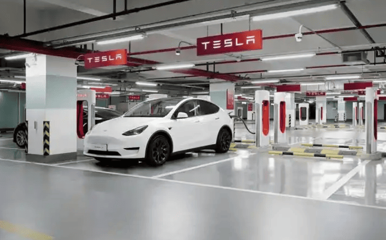
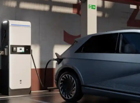
Fast Charging (DC) Mechanics: Bypassing the On-Board Charger
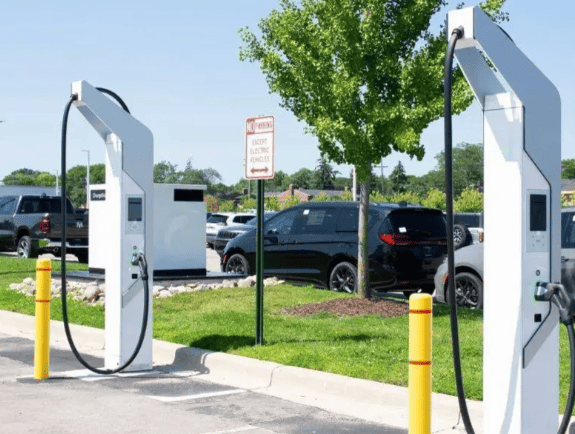
DC fast charging (DCFC) delivers 50-350 kW by moving conversion hardware to the station:
Step 1: High-Power Grid Connection
DCFC stations tap into industrial supplies:
- Europe: 400V 3-phase AC (up to 250A)
- North America: 480V 3-phase AC
- China: 380V 3-phase AC
Transformer substations often support multiple chargers.
Step 2: External Rectification & Regulation
Inside the charging cabinet, multi-stage conversion occurs:
- AC/DC Rectification: Silicon carbide (SiC) transistors convert AC to 650-1000V DC at >99% efficiency.
- DC Link Capacitors: Smooth voltage ripples.
- DC/DC Converters: Adjust voltage to the car’s battery level (e.g., step down 800V → 400V for older Nissans).
Cutting-edge stations: ABB Terra 360 uses modular 60 kW blocks. Four combine for 240 kW output.
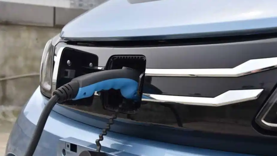
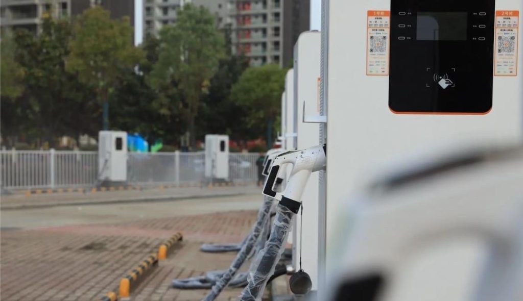
Step 3: Direct Battery Injection & Dynamic Control
The charger communicates directly with the BMS via CAN bus or PLC:
- Initial handshake: BMS shares battery voltage/temperature limits.
- Constant current phase: Delivers maximum power (e.g., 500A at 400V) until 80% SOC.
- Constant voltage phase: Gradually reduces current to avoid overvoltage.
Thermal management: Liquid-cooled cables (e.g., Tesla V4 Supercharger) prevent overheating at 600A+.
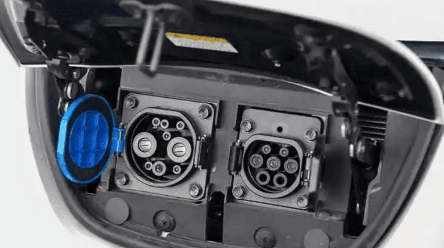
Regional Tech Variations:
| Market | Dominant Standard | Max Power | Communication Protocol |
|---|---|---|---|
| Europe | CCS Combo 2 | 350 kW | ISO 15118 (Plug & Charge) |
| North America | CCS1 / Tesla NACS | 250 kW | Proprietary (Tesla) / DIN 70121 |
| Japan | CHAdeMO | 150 kW | CHAdeMO 2.0 |
| China | GB/T 20234 | 900 kW* | GB/T 27930 |
| *GAC’s 480 kW station tested; 900 kW in development |
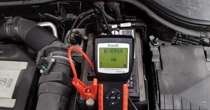
Battery Management System: The Charging “Brain”
The BMS protects the battery while optimizing charge speed:
Core Functions During Charging
- State Estimation:
- Calculates SOC (±3% accuracy) using coulomb counting + voltage modeling.
- Monitors SOH (state of health) by tracking capacity fade.
- Thermal Control:
- Activates cooling if cells exceed 40°C (liquid systems pump coolant at 4-6 L/min).
- Preheats batteries to 15°C+ in cold climates (drawing 3-5 kW from charger).
- Cell Balancing:
- Passive: Bleeds excess voltage from high cells via resistors (wastes energy).
- Active: Shuttles energy between cells (97% efficient, used in Lucid Air).
Safety Protocols:
- Isolates battery within 100 ms if voltage spikes >10%
- Detects insulation faults >100 Ω/V (EU ECE R100 standard)
Safety Systems: Protecting Users & Hardware
Charging involves multiple fail-safes:
Hardware Protections
- Isolation Monitoring Device (IMD): Shuts down if resistance between battery and chassis drops below 500 Ω/V.
- Contactor Welding Detection: Checks switch contacts for fusion during high-current charging.
- Ground Fault Circuit Interrupter (GFCI): Triggers at 5 mA leakage (US NEC Article 625).
Communication Safeguards
- Time-Out Protocols: Stops charging if BMS signals freeze for >3 seconds.
- Sequence Verification: Confirms relay closure order to prevent arcing.
Manufacturer Insight: DC chargers include metal-encased fault current limiters to contain 10 kA arc flashes.
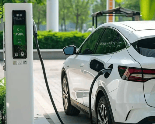
Regional Charging Workflow Differences
European Union: Plug & Charge Dominance
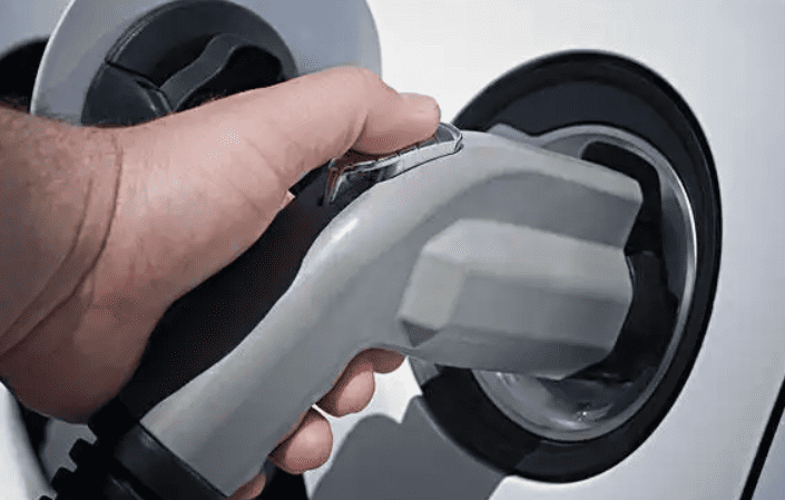
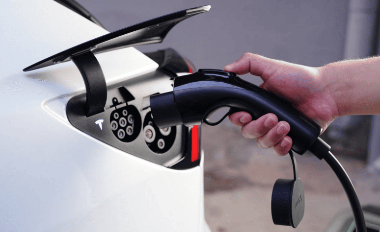
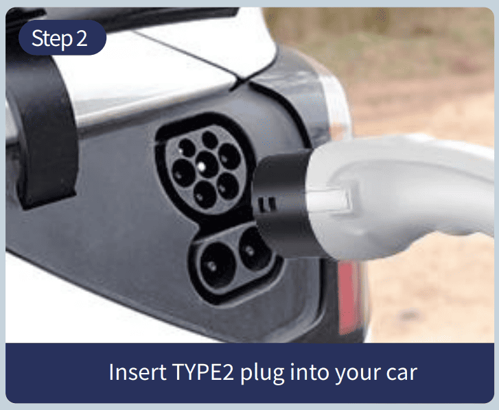
- Step 1: Driver plugs CCS Combo 2 connector.
- Step 2: ISO 15118 protocol auto-authenticates vehicle and billing via digital certificate.
- Step 3: Charging starts within 2 seconds—no app needed.
North America: Fragmented Systems
- Tesla: Seamless Supercharger handshake via proprietary CAN bus.
- CCS1 Stations: Requires app/credit card activation despite ISO 15118 support.
Japan: V2G-Capable CHAdeMO
- Bidirectional charging support: EVs feed power back to grid during peaks.
- Strict temperature monitoring: Charging pauses if ambient exceeds 40°C.
Future Tech: 800V Architectures & Beyond
Next-generation systems solve today’s limitations:
- 800V Platforms (Hyundai E-GMP, Porsche J1): Halve current for faster charging (350 kW → 10 min 10-80%).
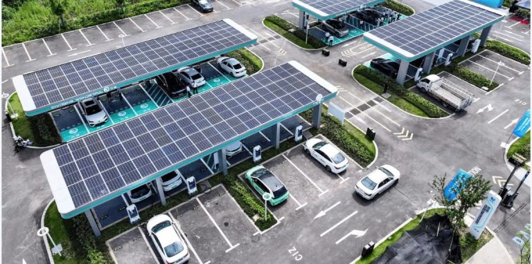
- Battery Buffering: Stations store off-peak grid energy to avoid demand charges.
- Robotic Chargers: Tesla’s Snake Bot prototypes autonomously plug in vehicles.
Manufacturer Takeaway: Prioritize SiC semiconductors and liquid cooling to support 500A+ currents.
“Charging isn’t just electrons moving—it’s a conversation between car, charger, and grid.”
— Senior Engineer, IONITY
Conclusion: Precision Engineering Enables Simplicity
EV charging transforms raw grid power into controlled battery energy through layered hardware and digital dialogue. While global standards differ (CCS in the West, GB/T in China, CHAdeMO in Japan), the core sequence remains: connect → communicate → convert → control. For drivers, this complexity hides behind plug-and-charge ease; for engineers, it represents one of electrification’s most sophisticated dances of physics and data.
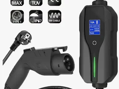
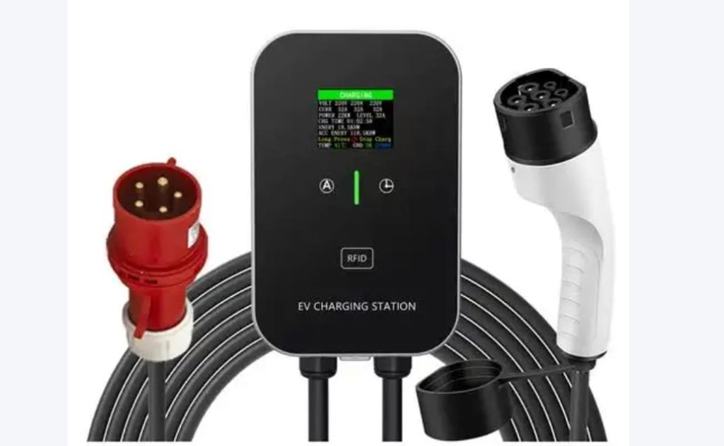
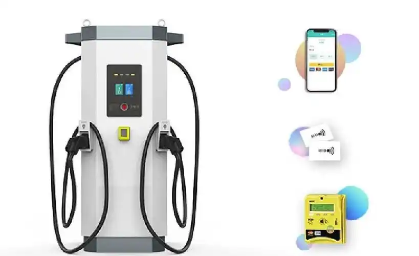
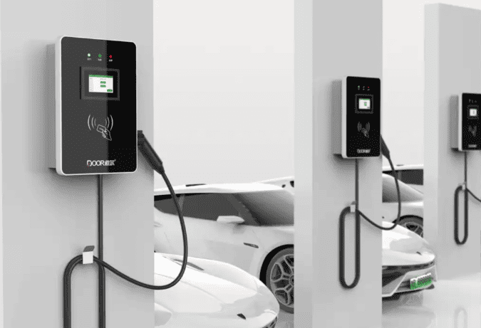
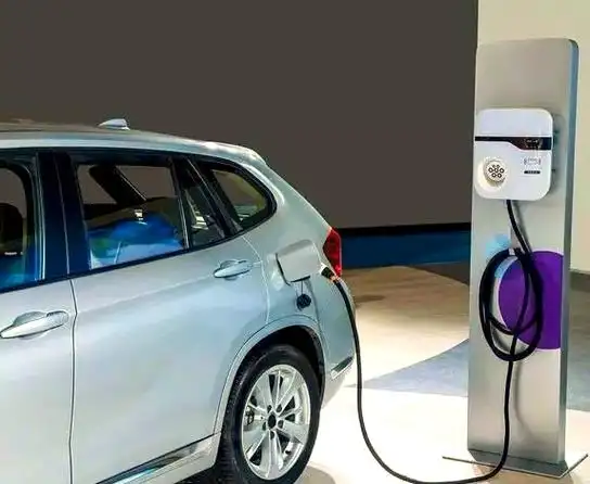
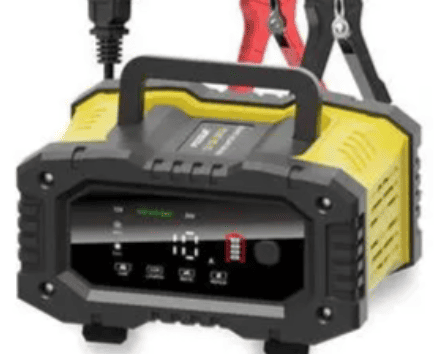
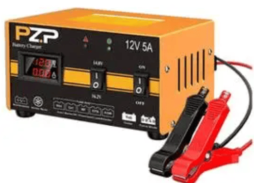
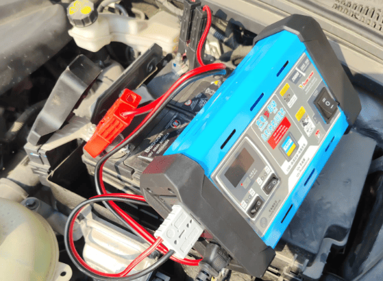
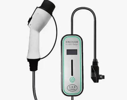
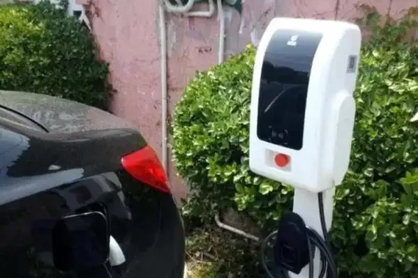
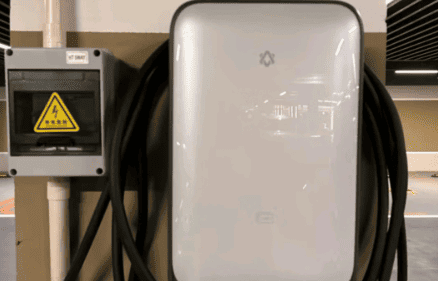
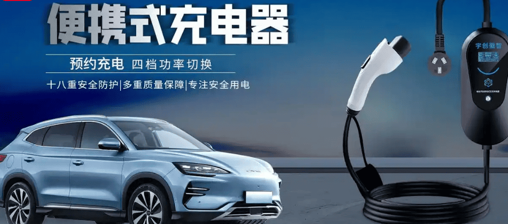
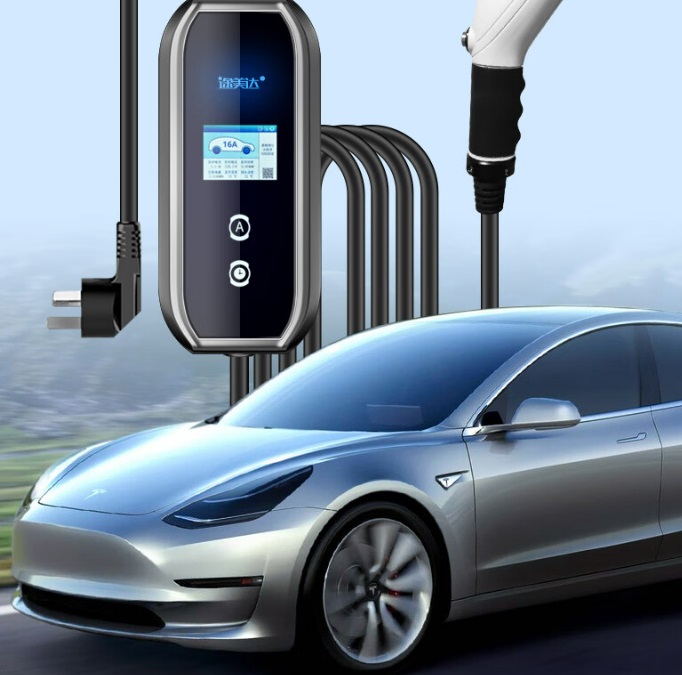
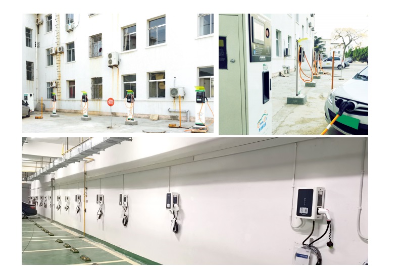
Recommend Slow Charger Products:
Charging pile:
Contact Us
Whatsapp/Mobile: +86 18019762979
Email: sales@lkmixer.com