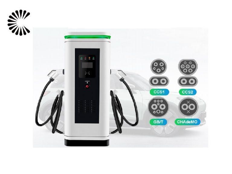
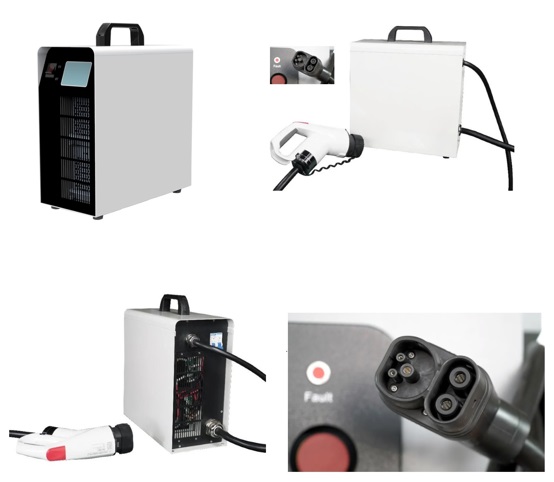
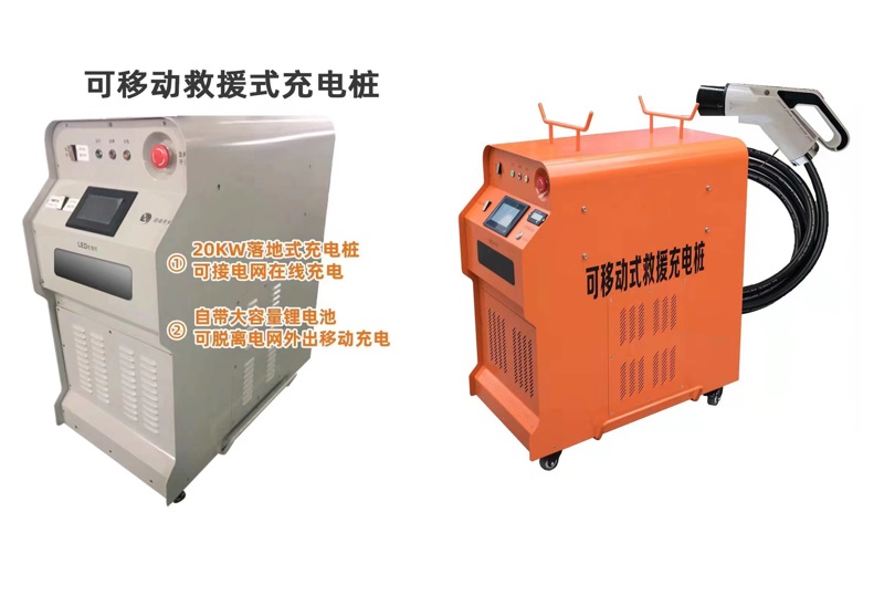
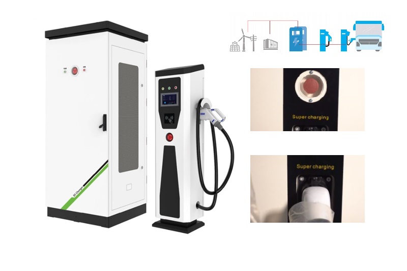
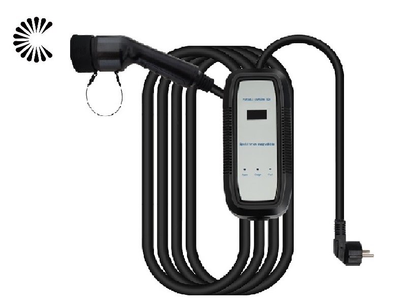
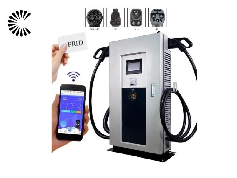
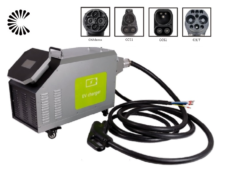
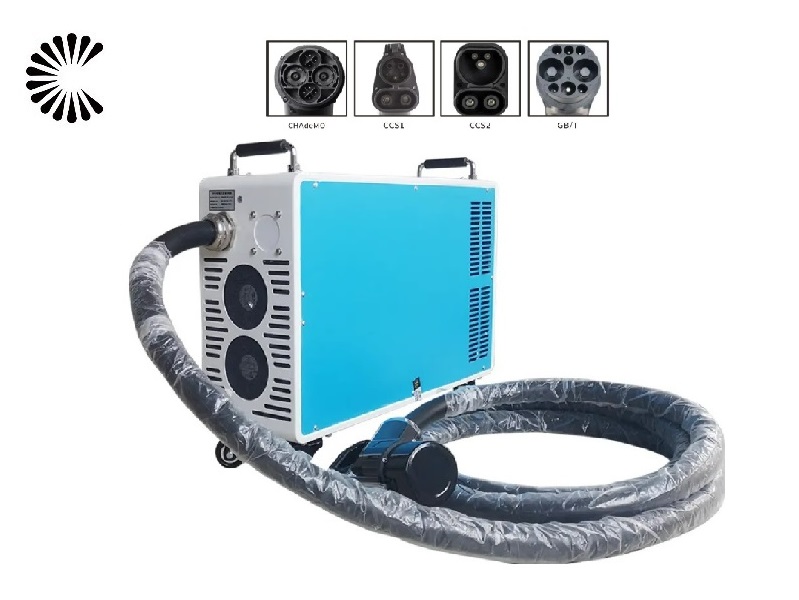
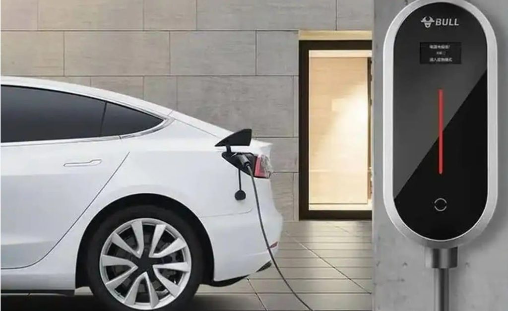
DC Mobile EV Charger

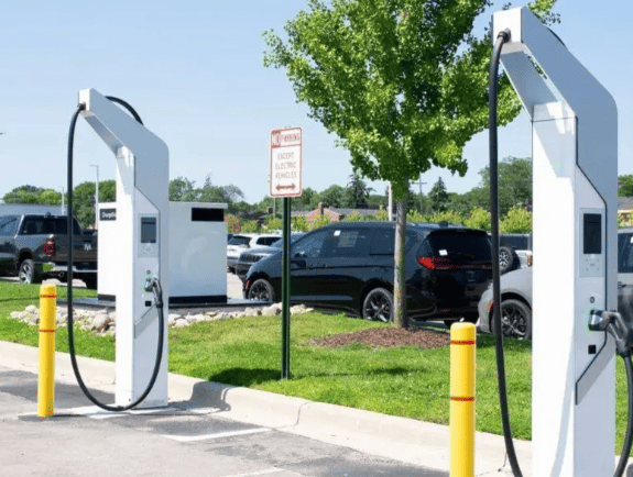
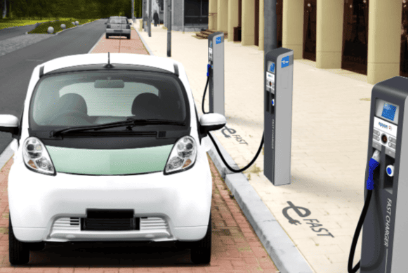
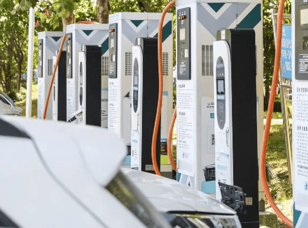
Highway gas, sevice station, Parking garage, commercial operators, EV infrastructure operations and service providers, EV dealer workshops
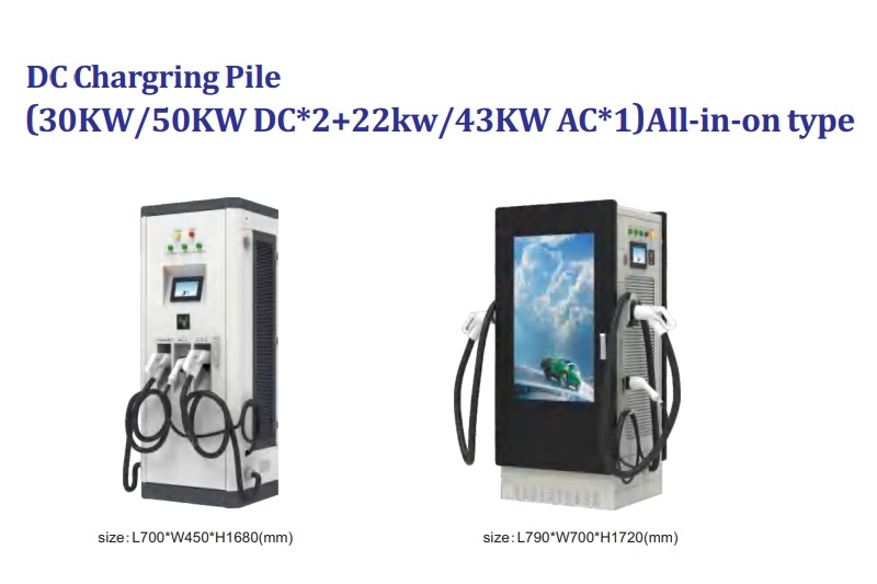
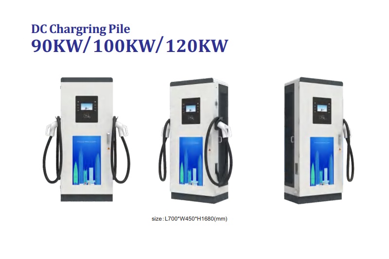
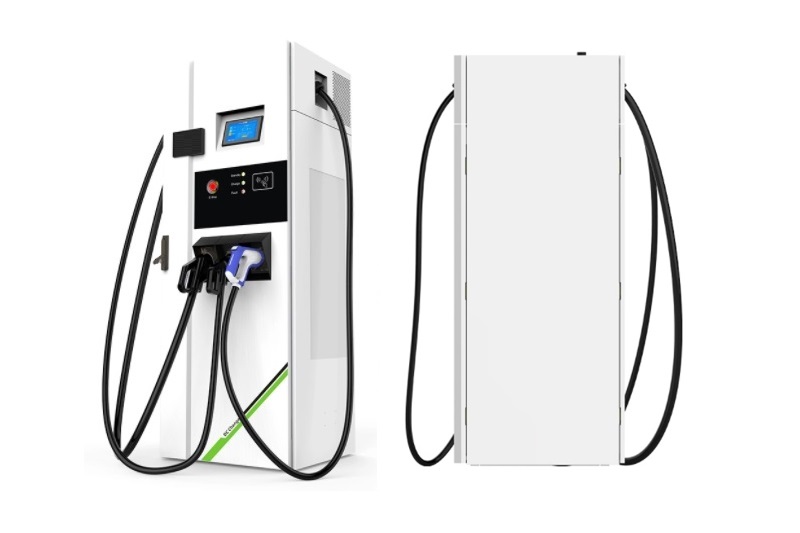
DC EV Charger
DC Mobile EV Charger Product Overview

The present utility model relates to a movable new energy vehicle charging device, comprising an energy storage module, a power input module, a power output module, a DC/DC low-voltage power module, a human-machine interface, a temperature control system, a wireless communication module, a multimedia service system, an emergency stop device, and a mobile carrying platform. The energy storage module includes a battery pack and a BMS. The energy storage module supplies power to the power output module and the DC/DC low-voltage power module. The DC/DC low-voltage power module provides low-voltage power to the low-voltage circuits of the device. The power input module enables the grid to charge and store energy in the device. The power output module enables the charging and energy storage for new energy vehicles. This device addresses the limitations of fixed charging facilities for new energy vehicles, achieving mobility, convenience, and low-cost energy storage for charging equipment, thereby providing a portable, low-cost, and efficient charging solution for the new energy vehicle charging market and service sector.
A Movable New Energy Vehicle Charging Device
Technical Field
The present utility model relates to the field of new energy vehicle charging services, particularly to a movable new energy vehicle charging device.
Background Technology
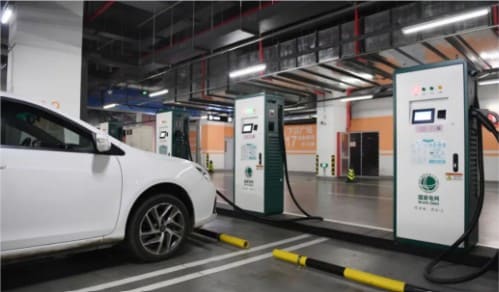
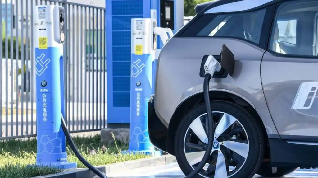
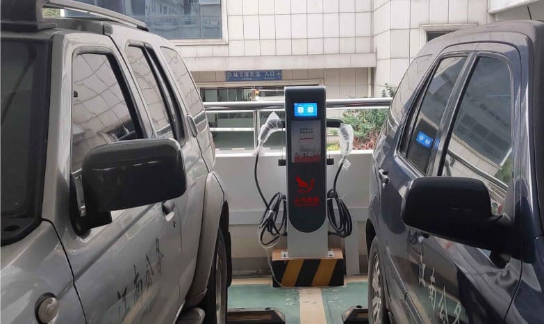
With the continuous development of new energy vehicles, their market share is steadily increasing. This has led to the challenge of charging infrastructure for new energy vehicles, giving rise to the new energy vehicle charging industry, with both sectors mutually reinforcing each other. Currently, fixed charging piles/stations are widely used in the market to meet the demand for recharging the power batteries of new energy vehicles.
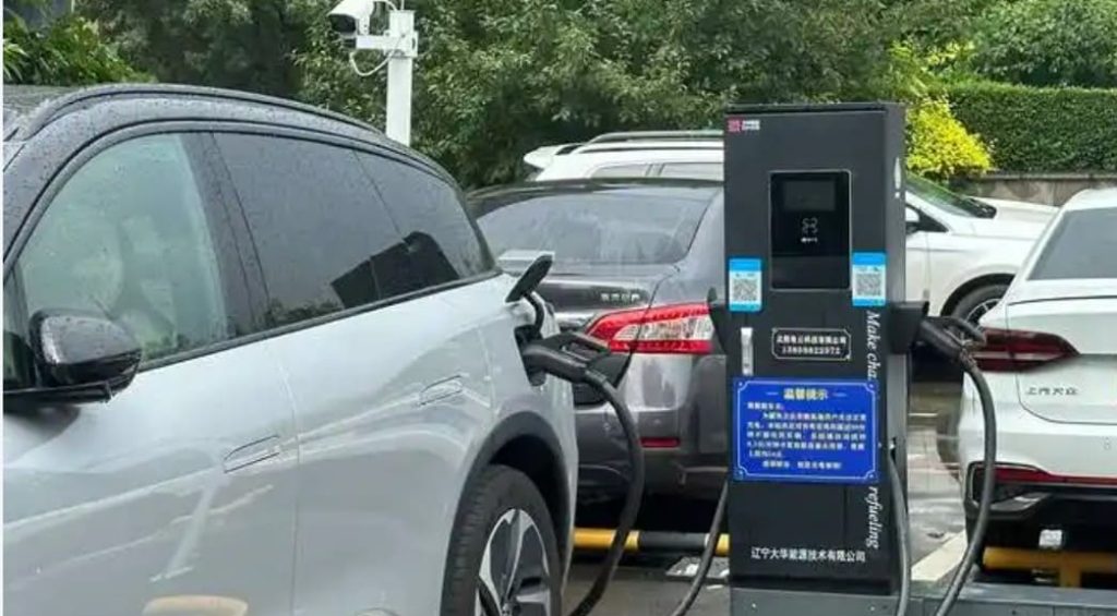
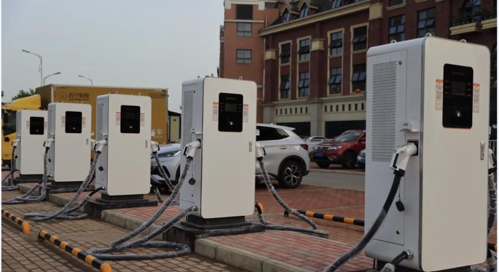
In recent years, the charging pile industry has developed rapidly with strong government support, but it still falls short of market demand. Additionally, issues such as site planning and grid upgrades are required. Movable charging devices have emerged to address these challenges, offering high efficiency, flexibility, speed, and safety, thereby improving the new energy vehicle charging and after-sales service sectors. These devices not only meet the charging needs of new energy vehicles in various environments but also avoid the drawbacks of fixed charging equipment, presenting broad market prospects. Therefore, there is an urgent need for a movable new energy vehicle charging device in both the industry and aftermarket.
Utility Model Content
The problem to be solved by the present utility model is to provide a movable new energy vehicle charging device that is efficient, flexible, fast, safe, and facilitates quick charging for new energy vehicles in different environments.
To achieve the above objective, the present utility model adopts the following technical solution:
The present utility model provides a movable new energy vehicle charging device, comprising an energy storage module, a power input module, a power output module, a DC/DC low-voltage power module, a human-machine interface, a temperature control system, a wireless communication module, a multimedia service system, an emergency stop device, and a mobile carrying platform. The energy storage module includes a high-voltage port connected to the power input module, a second high-voltage port connected to the power output module, and a third high-voltage port connected to the DC/DC low-voltage power module. The DC/DC low-voltage power module is connected via low-voltage ports to the energy storage module, power input module, power output module, human-machine interface, temperature control system, wireless communication module, multimedia service system, and emergency stop device, providing low-voltage DC power. The communication ports of the energy storage module, power input module, power output module, DC/DC low-voltage power module, human-machine interface, temperature control system, wireless communication module, multimedia service system, and emergency stop device are connected via a bus.
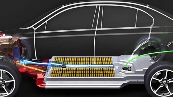
Further, the energy storage module includes a battery module and a BMS. The battery module serves as the primary energy storage and power source for the device.
Further, the battery module may use new power batteries or recycled secondary-use power batteries. The BMS monitors the status of the battery module in real time, including state information, environmental data, charge/discharge information, and operational control.
Further, the power input module has a high-voltage port connected to the grid and another high-voltage port connected to the energy storage module, enabling charging and energy storage for the energy storage module.
Further, the power output module has a high-voltage port connected to the energy storage module and another high-voltage port connected to the device to be charged. The power output module provides adjustable high-voltage DC output.
Further, the emergency stop device can perform emergency shutdown protection for the movable new energy vehicle charging device in critical situations.
Further, the energy storage module, power input module, power output module, DC/DC low-voltage power module, human-machine interface, temperature control system, wireless communication module, multimedia service system, and emergency stop device are mounted on the mobile carrying platform. The mobile carrying platform includes a carrying platform, a traction device, and a parking lock device, enabling mobility and reliable parking braking for the device. The multimedia service system can autonomously deliver service information. The wireless communication module enables wireless interconnection between the movable new energy vehicle charging device, big data platforms, and end-users.
Further, the traction device includes manual traction, equipment traction, and motor-powered traction, enabling multiple traction methods for the device.
The present utility model offers the following advantages:
Compact structure, low-cost energy storage, flexible mobility, high efficiency, and speed. It not only enables low-cost energy storage during off-peak electricity periods but also provides safe and fast charging for new energy vehicles in various environments.
Detailed Implementation
The technical solutions of the embodiments of the present utility model will be clearly and completely described below with reference to the accompanying drawings. Obviously, the described embodiments are only a part of the embodiments of the present utility model, not all of them. Based on the embodiments of the present utility model, all other embodiments obtained by those of ordinary skill in the art without creative efforts shall fall within the protection scope of the present utility model.
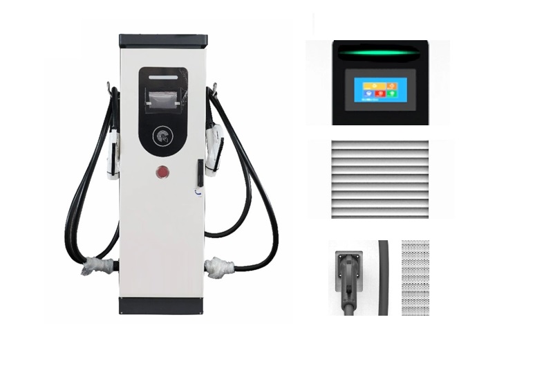
As shown in Figures 1 and 7, the present utility model provides a movable new energy vehicle charging device, including: the power input module 100, energy storage module 200, power output module 300, DC/DC low-voltage power module 400, multimedia service system 500, temperature control system 600, human-machine interface 700, wireless communication module 800, emergency stop device 900, all mounted on the mobile carrying platform 1100. The mobile carrying platform 1100 serves as the weight-bearing and transportation platform for the device.
Figure 2 is a schematic diagram of the high-voltage system structure of the present utility model. The power input module 100 has one high-voltage port connected to the grid AC power and another high-voltage port connected to the energy storage module 200, enabling charging and energy storage for the energy storage module 200. The second high-voltage port of the energy storage module 200 is connected to the power output module 300, enabling power output. The third high-voltage port of the energy storage module 200 is connected to the DC/DC low-voltage power module 400, supplying power to the DC/DC low-voltage power module.
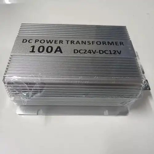
Figure 3 is a schematic diagram of the low-voltage system structure of the present utility model. The DC/DC low-voltage power module 400 is connected via low-voltage lines to the power input module 100, BMS 202, power output module 300, multimedia service system 500, temperature control system 600, human-machine interface 700, wireless communication module 800, and emergency stop device 900, providing low-voltage power to the low-voltage circuits. The low-voltage power may be DC12V or DC24V. The BMS 202 performs signal detection and charge/discharge balancing for the battery module 201.
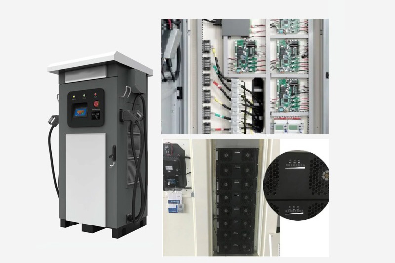
Figure 4 is a schematic diagram of the power input module structure of the present utility model. The power input module 100 includes: an AC power input interface 101, an AC/DC converter 102, a power output unit 103, a contactor 104, a connection lock 105, and a charging controller 106. The AC power input interface 101 connects the grid to the charging circuit of the device. The connection lock 105 is installed on the AC power input interface 101. The charging controller 106 monitors data and controls the connection lock 105 and contactor 104 to ensure safe charging and energy storage for the device.
Figure 5 is a schematic diagram of the power output module structure of the present utility model. The power output module 300 includes: a contactor 301, a DC/DC boost module 302, an adjustable high-voltage DC charger 303, a DC high-voltage output interface 304, a discharge controller 305, and a connection lock 306. The connection lock 306 is installed on the DC high-voltage output interface 304. The discharge controller 305 monitors data and controls the connection lock 306 (locking/unlocking) and the contactor 301 (on/off) to ensure safe discharge for the device.
Figure 6 is a network topology diagram of the movable new energy vehicle charging device of the present utility model. The device is equipped with a CAN bus network, mainly including: the power input module 100, BMS 202, DC/DC low-voltage power module 400, power output module 300, multimedia service system 500, temperature control system 600, human-machine interface 700, wireless communication module 800, and emergency stop device 900. The multimedia service system 500 autonomously delivers service information. The temperature control system 600 intelligently regulates the operating temperature of the device. The human-machine interface 700 displays charging/discharging information and controls the operational status of the device. The wireless communication module 800 enables real-time information sharing between the device, big data platforms, and end-users. The emergency stop device 900 provides shutdown protection in emergencies.
Figure 7 is a schematic diagram of the mobile carrying platform of the present utility model. The mobile carrying platform 1100 includes: a carrying platform 1101, a traction device 1102, and a parking lock device 1103. The traction device 1102 includes equipment traction 1102a, manual traction 1102b, and motor-powered traction 1102c. The motor-powered traction 1102c can be optionally configured as needed.
Through the above optimization, the movable new energy vehicle charging device features a compact structure, low-cost energy storage, flexible mobility, high efficiency, and speed. It not only enables low-cost energy storage during off-peak periods but also provides safe and fast charging for new energy vehicles in various environments.
Contact Us
Contact Us
Whatsapp/Mobile: +86 18019762979
Email: sales@lkmixer.com
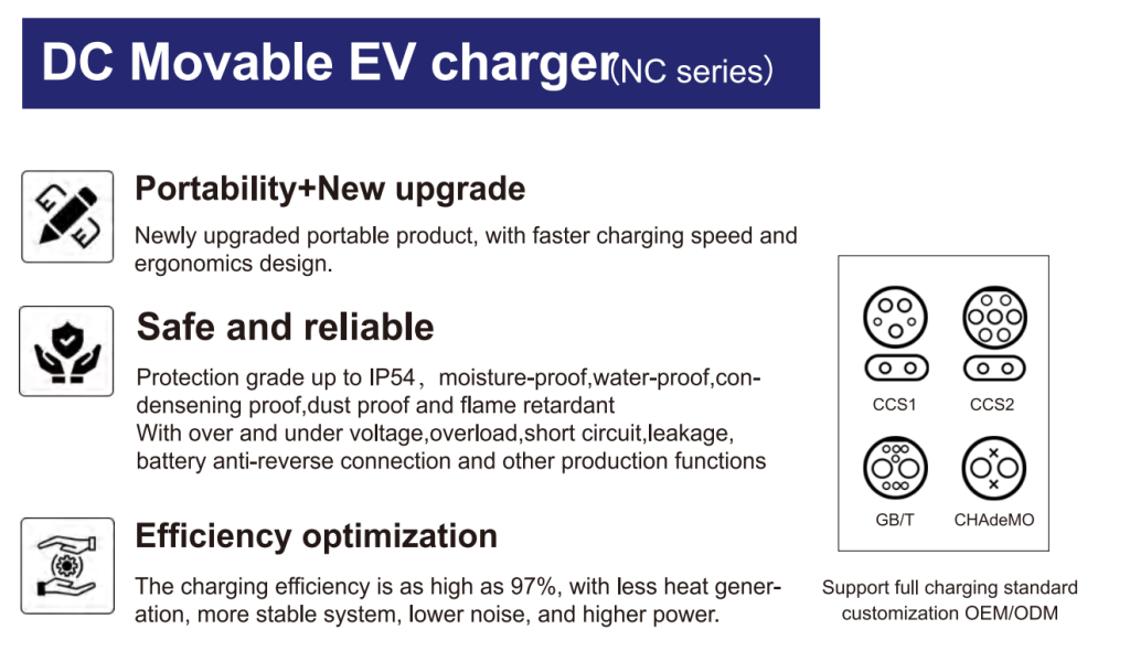
DC Mobile EV Charger Feature
The device comprises an energy storage module, a power input module, a power output module, a DC/DC low-voltage power module, a human-machine interface, a temperature control system, a wireless communication module, a multimedia service system, an emergency stop device, and a mobile carrying platform. The energy storage module includes a high-voltage port connected to the power input module, a second high-voltage port connected to the power output module, and a third high-voltage port connected to the DC/DC low-voltage power module. The DC/DC low-voltage power module is connected via low-voltage ports to the energy storage module, power input module, power output module, human-machine interface, temperature control system, wireless communication module, multimedia service system, and emergency stop device, providing low-voltage DC power. The communication ports of the energy storage module, power input module, power output module, DC/DC low-voltage power module, human-machine interface, temperature control system, wireless communication module, multimedia service system, and emergency stop device are connected via a bus.
The movable new energy vehicle charging device according to claim 7, characterized in that the traction device includes manual traction, equipment traction, and motor-powered traction.
The movable new energy vehicle charging device according to claim 1, characterized in that the energy storage module includes a battery module and a BMS.
The movable new energy vehicle charging device according to claim 2, characterized in that the battery module may use new power batteries or recycled secondary-use power batteries, and the BMS monitors the status of the battery module in real time.
The movable new energy vehicle charging device according to claim 1, characterized in that the power input module has a high-voltage port connected to the grid and another high-voltage port connected to the energy storage module, enabling charging and energy storage for the energy storage module.
The movable new energy vehicle charging device according to claim 1, characterized in that the power output module has a high-voltage port connected to the energy storage module and another high-voltage port connected to the device to be charged, providing adjustable high-voltage DC output.
The movable new energy vehicle charging device according to claim 1, characterized in that the emergency stop device performs emergency shutdown protection for the movable new energy vehicle charging device in critical situations.
The movable new energy vehicle charging device according to claim 1, characterized in that the energy storage module, power input module, power output module, DC/DC low-voltage power module, human-machine interface, temperature control system, wireless communication module, multimedia service system, and emergency stop device are mounted on the mobile carrying platform, which includes a carrying platform, a traction device, and a parking lock device.
Transportation
In the course of transportation, the charger should be packed firmly and intact in
a solid wooden packing box, and the direction of loading and unloading should be marked.
The charger should not be stored and transported upside down. In the course of
transportation, corresponding tightening measures should be taken to avoid strong
vibration and bump damage to the outer packaging of equipment. After arrival of the
goods, user should check whether there is any damage. If there is any transport damage,
user should consult with the transport party or our company to solve it. Check whether
the contents in the box are in conformity with the packing list immediately after
opening the box.
The packaged equipment should be stored in the room where the relative humidity is
less than 80% and the ambient air temperature is -20℃ to +55℃. Storage places should
be dry, clean and airy, and can prevent the invasion of harmful gases. It is strictly
forbidden to store corrosive articles in the same place.
Note: It is strictly forbidden for non-professionals to disassemble equipment
components.

Certification
Our Factory have certifications such as CE ISO Certifications. TUV /UL /CE Certificated for Overseas on cable and wire.

Maintenance
- Charger body is easy to be fixed with anchor bolts to prevent it from inclining
and dithering due to external and human factors. - Shading and rainproof measures should be taken for chargers. It is suggested
to install shelters outdoors. - Check regularly whether all bolts in chargers are tightened, whether the connecting wires are loosened or not, or the connection is not firm, etc.
- Check for short circuit.
- Check whether the emergency stop button is available.
- Attention should be paid to lightning protection to ensure effective shielding
and reliable grounding of chargers. - When in use, the output voltage and current of the charger should be controlled within the nominal range to ensure that the charger works in the state of maximum efficiency.
- When the charger stops using, the charging output should be stopped first, then the cable should be wrapped and put back in place.
Note: During the transportation, the chargers should be packed firmly and the
direction of loading and unloading should be marked. It is forbidden to store and
transport chargers upside down. Corresponding tightening measures should be taken
to avoid strong vibration and turbulence damage to the outer packaging of equipment.
Why choose us
- Decades of Experiences: As a Chinese academy of sciences park high-tech enterprise and manufactory, our factory establised since 2002, with over 10 years factory development, our factory became famous brand in China. We believe new energy is the future, better to environment and more economical to our life. We are an integrated hi -tech electronic company. “Passion, Honesty, Sound service, Keen cooperation and Development” are our goals. We are here expecting friends all over the world!
- Various Charging Products: Full range of charging products as well as charger accessories. Provide full support to customer after-sale services. Most of the model of produts are able to be customized.
- For all the products that we shipped have 1 year warranty period as well as life time spare parts and accessories with competitive price .
- Accept customized OEM ODM products.
- Experienced foreign trade team to handle the shipment and after-sale services.
- Efficient and fast supply chain.
Factory Introduction
Our factory is a national high-tech enterprise as well as tech little giant enterprise of Hubei
Province, which is specialized in R&D production, marketing of smart charging stations, as well
as the overall charging system solutions. The industrial Park has covered an area of 56,000m2.
The company has nearly 150 employees,30% of which are core R&D staff.
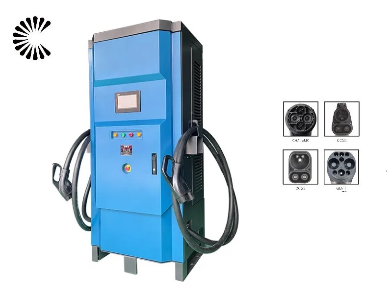
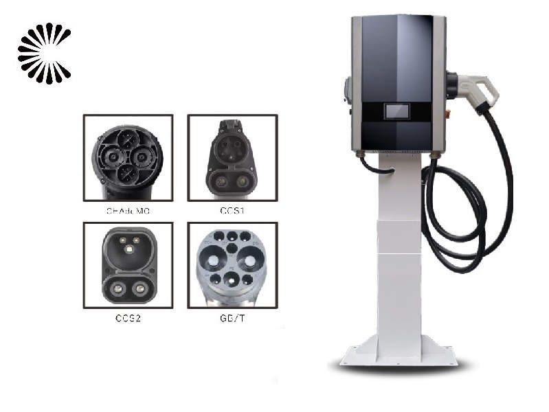
Factory has created a complete industrial chain and covered all the four international charging
standards as GB/T, CCS2, CCS1 as well as CHAdeMO. Products covered three series of Ac DC
and super charging systems. Its brand EV chargers have already been applied to more than200
cities in China and over 27 countries and regions around the world. By virtue of over 20 years
R&D experiences of electronic power control technology, the company has developed multiple
independent intellectual property rights of core technologies such as the whole charger design,
charging control system, billing and metering system, remote monitoring and management
platform and mobile terminal charging service, which help it accumulated enriched experience in R &D and manufacturing fields.
| Certificate: | CE RoHS FCC Certificate | Warranty: | 12 Months |
| Input Voltage: | 110V-380V | Output Voltage: | 0-750V |
| Working Temperature: | -25℃-55℃ | Application: | Home Use/Commercial Use |
| OEM Service: | Color,Logo,Package, cable length, cable color | Supply Ability : | 4000 Piece/Pieces per Week |
| Packaging & Delivery: | Shanghai Port | Capacity | 4000 Piece/Pieces per Week |
| Lead Time: | Quantity(units) 1 – 5 5 working days | Factory Type | Supplier |
| Country / Region | China/Gungdong | Main Products | EV Charging Station, EV Charging Cable, EV Charging Connector |
| Factory employees | Over 100 people | Total Annual Revenue | Above US$100 Million |
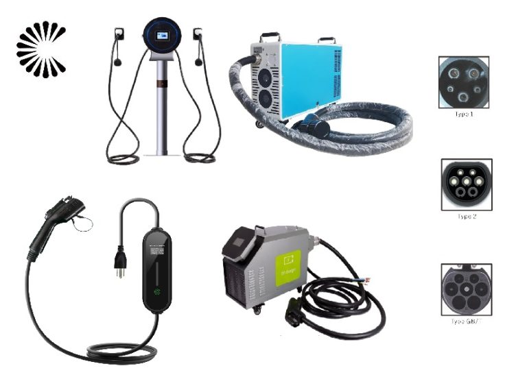
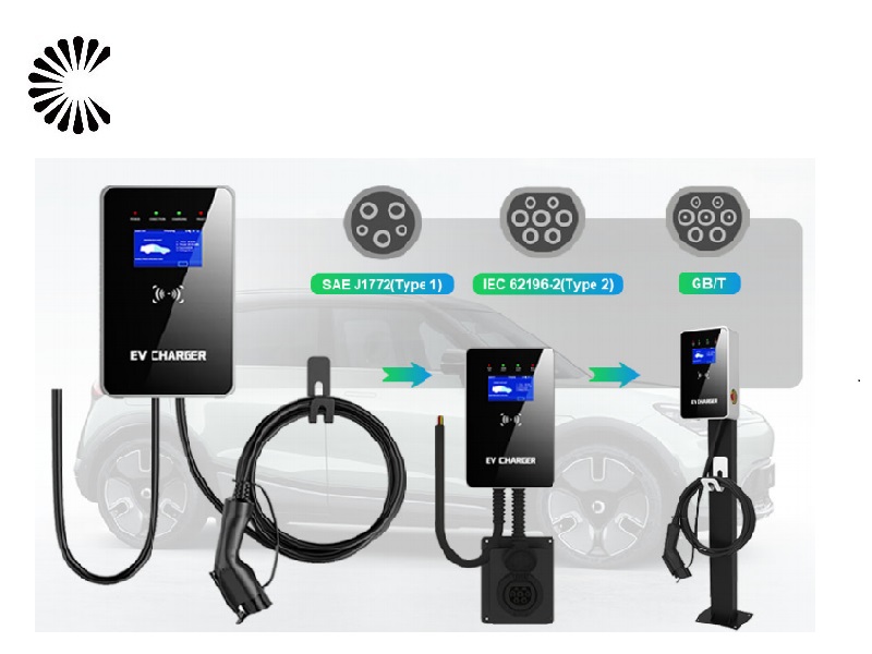
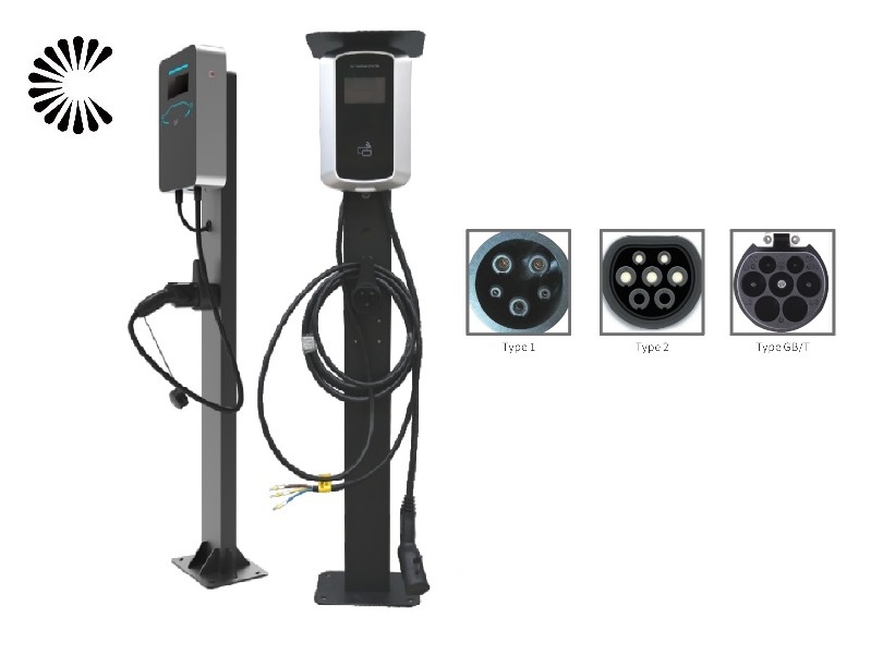
| Main Markets | Europe South America | Connection: | type 1 or 2 plug |
| Mass production price | Negotiable | Charger Capacity | 3.5kw~480kw |
| Current | DC/AC | Plug type | Type 1,2,CHAdemo/CCS-2/CCS-1 |

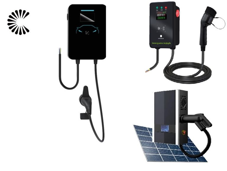
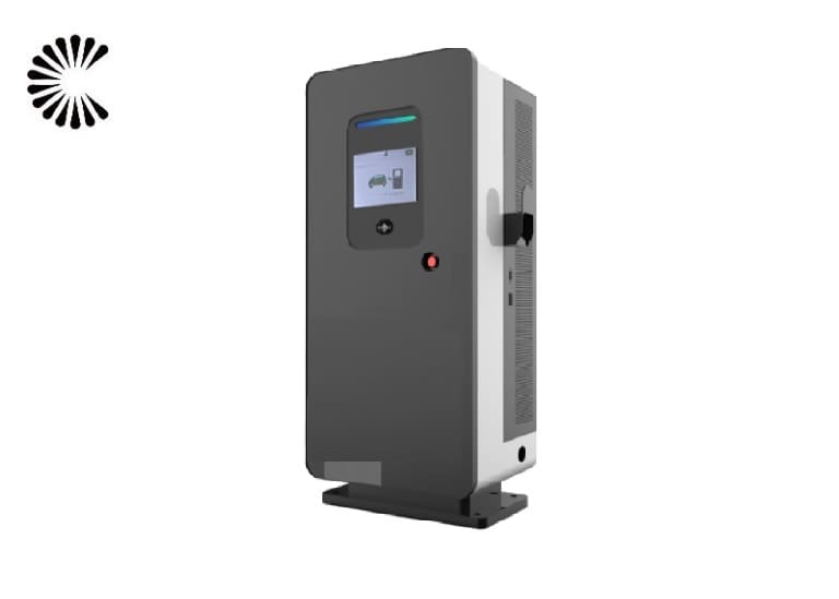
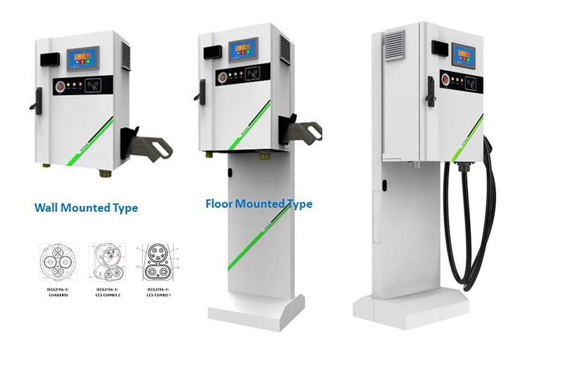
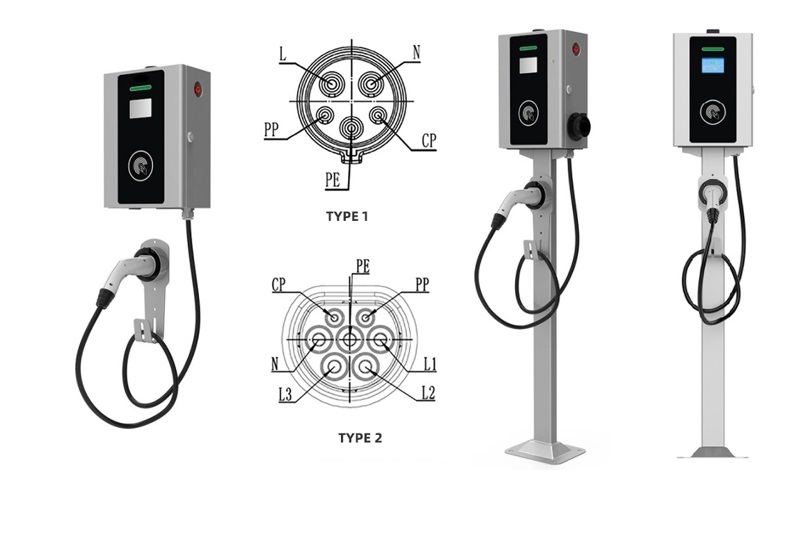
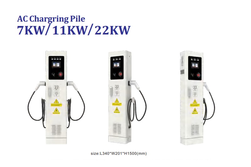
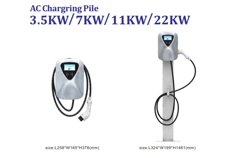
3.5~22KW EV Charger
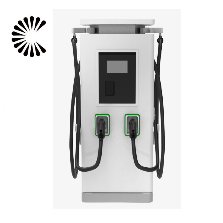
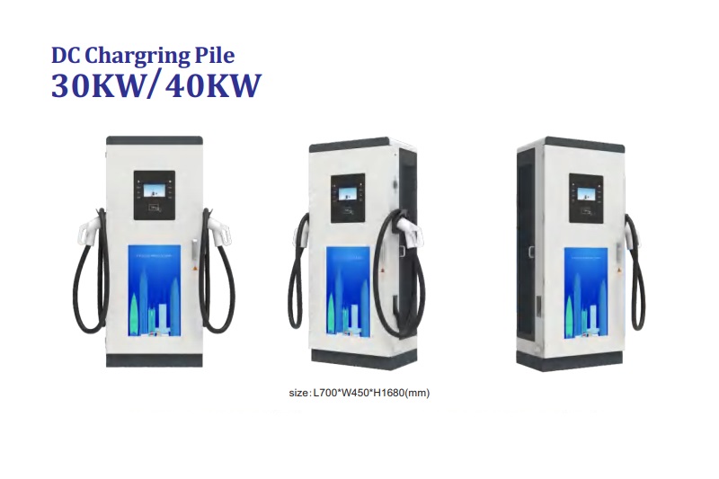
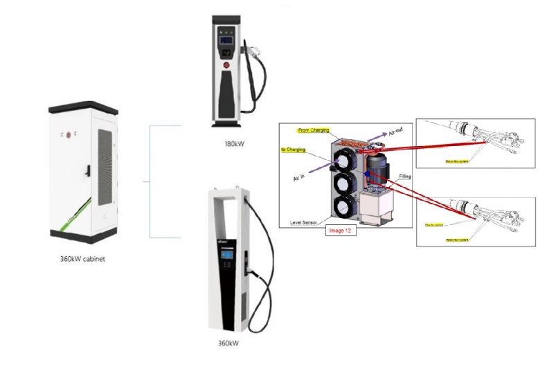
60KW EV Charger
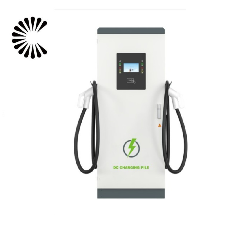
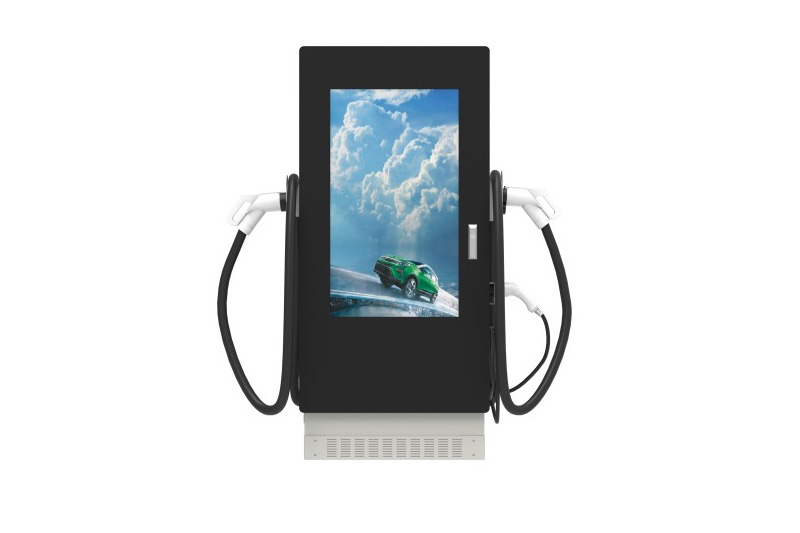
100KW~150KW EV Charger
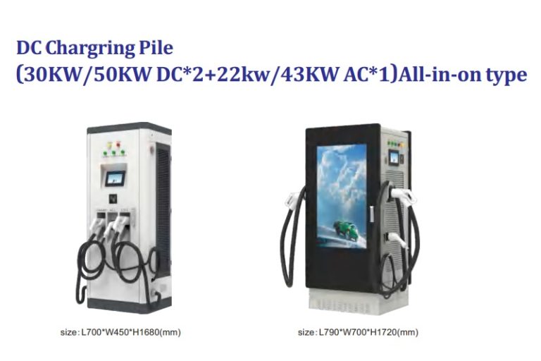
DC Mobile EV Charger Wholesale Manufacturer In China
As a leading DC Mobile EV Charger manufacturer, we take pride in providing cutting-edge charging solutions for electric vehicles. With a focus on quality and innovation, we ensure that our chargers meet the highest industry standards, delivering rapid and reliable charging experiences. Our team of dedicated engineers works tirelessly to enhance the efficiency and user-friendliness of our products, promoting sustainable transportation for a greener future. From public charging stations to private installations, we cater to diverse needs, empowering EV drivers to embrace a cleaner, more sustainable lifestyle. Join us in driving the electric revolution forward with our state-of-the-art charging solutions.
Contact Us
Contact Us
Whatsapp/Mobile: +86 18019762979
Email: sales@lkmixer.com
Related Products


Related Articles


Contact Us
Frequently Asked Questions (Click to see more FAQ)
-
Are you a factory or trading company?
We are a professional manufacturer of new and sustainable energy applications for over 20 years.
-
What is the warranty?
Warranty period is 12 months. In this period, we will supply technical support and replace the new parts by free,customers are in charge of delivery.
-
What is the packing method?
Generally, we pack our goods in brown cartons. If you have legally registered patent, we can pack the goods in your branded boxes after getting your authorization letters.
-
What is your terms of payment?
T/T 50% as deposit, and 50% before delivery. We’ll show you the photos of the products and packages before you pay the balance.
-
What is your terms of trade?
EXW, FOB, CFR, CIF, DAP,DDU,DDP
-
How about your delivery time?
Generally, it will take 3 to 7 working days after receiving your advance payment. The specific delivery time depends on the items and the quantity of your order.
-
Can you produce according to the samples?
Yes, we can produce by your samples or technical drawings. We can build the molds and fixtures.
-
What is your sample policy?
We can supply the sample if we have ready parts in stock, but the customers have to pay the sample cost and the courier cost.
-
Do you test all your goods before delivery?
Yes, we have 100% test before delivery.
-
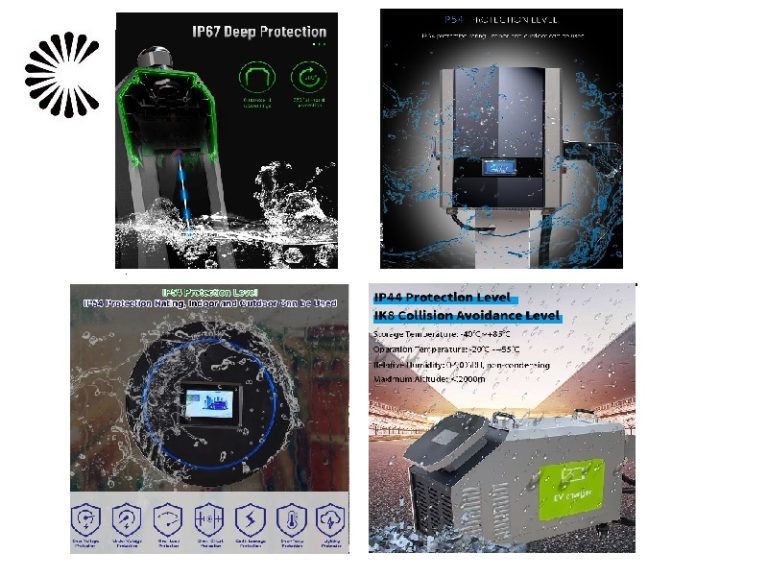
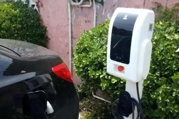
What’s the difference between Movable Charger and Wallbox Charger?
In addition to the obvious appearance difference, the main protection level is different: wallbox charger protection level is IP54, available outdoors;And the Movable Charger protection level is IP43, rainy days and other weather can not be used outdoors.
-
How fast does a 150kW charger charge?
The 150KW EV Charger offers numerous advantages that make it a game-changer in the world of electric vehicle charging. Here are some of the key benefits:
Lightning-Fast Charging: The 150KW EV Charger’s high-power capacity enables it to charge electric vehicles at incredibly fast rates. With such rapid charging speeds, EV owners can significantly reduce the time spent waiting at charging stations, making long journeys and commutes more convenient and time-efficient.
Reduced Downtime: Due to its quick charging capabilities, the 150KW EV Charger minimizes the downtime for electric vehicles. This is especially beneficial for commercial and fleet operators who rely on their vehicles for daily operations. Less time spent charging means more time on the road, maximizing productivity and profitability.
Universal Compatibility: The 150KW EV Charger is designed to be compatible with a wide range of electric vehicles. From compact city cars to larger electric SUVs, this charger can cater to diverse charging needs, making it versatile and accessible for various electric vehicle owners.
Optimal Battery Health: The charger is equipped with advanced charging protocols and safety features that prioritize the health of the electric vehicle’s battery. By preventing overcharging and overheating, the charger helps extend the battery’s lifespan and ensures long-term performance and efficiency.
Future-Proof Investment: As electric vehicles and charging technology continue to evolve, the 150KW EV Charger provides a future-proof charging solution. With its high-power capacity, it is well-equipped to handle the charging demands of upcoming electric vehicle models that may have larger batteries and faster charging capabilities.
Environmentally Friendly: Embracing electric mobility is a significant step towards reducing greenhouse gas emissions and combatting climate change. By encouraging the use of electric vehicles, the 150KW EV Charger plays a vital role in promoting sustainable transportation and contributing to a cleaner, greener environment.
User-Friendly Experience: Despite its high-power capacity, the 150KW EV Charger is designed with a user-friendly interface and intuitive controls. EV owners can easily initiate and monitor the charging process, making it accessible to both experienced electric vehicle users and those new to the technology.
Supporting Charging Infrastructure: The adoption of the 150KW EV Charger encourages the development of a robust charging infrastructure. As more of these high-power chargers are deployed, it enhances the charging network’s efficiency and coverage, making electric vehicle adoption more feasible for a broader audience.
In summary, the 150KW EV Charger’s advantages lie in its rapid charging speed, universal compatibility, battery health protection, and its contribution to environmental sustainability. By investing in this high-power charging solution, we can pave the way for a more efficient, eco-friendly, and convenient electric vehicle charging ecosystem. -
What does 150kW charger mean?
A 150 kW charger refers to an electric vehicle (EV) charger with a power capacity of 150 kilowatts. The “kW” stands for kilowatts, which is a unit of power used to measure the rate at which electrical energy is transferred or consumed.
In the context of EV charging, the power capacity of the charger determines how quickly it can recharge an electric vehicle’s battery. A 150 kW charger is considered a high-power charger, capable of delivering a significant amount of electricity to the vehicle’s battery in a short amount of time.
To put it simply, a 150 kW charger can charge an electric vehicle at a rate of 150 kilowatts per hour. The higher the charger’s power capacity, the faster the charging process, reducing the time required to replenish the vehicle’s battery.
High-power chargers like the 150 kW charger are particularly useful for long-distance travel or quick pit stops during road trips. They enable electric vehicle owners to charge their vehicles rapidly, making electric mobility more convenient and practical for everyday use.
As electric vehicle technology continues to advance, high-power chargers like the 150 kW charger play a crucial role in supporting the growth of electric mobility and fostering a cleaner, greener transportation future. -
What voltage for 150kW charger?
The voltage for a 150 kW charger typically depends on the specific design and specifications of the charger. Electric vehicle (EV) chargers can operate at various voltage levels, but the most common ones for high-power chargers like the 150 kW charger are 400-480 volts for direct current (DC) fast charging.
DC fast chargers, also known as Level 3 chargers, are capable of delivering high-power charging rates to quickly recharge electric vehicle batteries. They are commonly used for fast-charging stations along highways, at public charging stations, and in commercial settings.
While the typical voltage range for a 150 kW DC fast charger is around 400-480 volts, it’s important to note that different manufacturers or regions may have slightly different voltage specifications based on their electrical infrastructure and safety standards.
As electric vehicle technology continues to evolve, it’s possible that new charger designs may emerge with different voltage requirements or innovative charging capabilities. Therefore, when considering a 150 kW charger or any EV charger, it’s essential to review the manufacturer’s specifications and ensure compatibility with the local electrical system and the electric vehicles you intend to charge. -
How long does a 150kW charger take to charge a car?
The time it takes for a 150 kW charger to charge a car depends on the battery capacity of the vehicle and its current state of charge. Charging time is typically measured in kilowatt-hours (kWh) and can vary from one electric vehicle to another.
To estimate the charging time using a 150 kW charger, you can use the following formula:
Charging Time (in hours) = Battery Capacity of the Electric Vehicle (in kWh) / Charging Rate of the EV Charger (in kW)
For example, let’s say an electric vehicle has a battery capacity of 60 kWh and is connected to a 150 kW charger:
Charging Time = 60 kWh / 150 kW ≈ 0.4 hours
In this case, it would take approximately 0.4 hours (or 24 minutes) to fully charge the electric vehicle using the 150 kW charger.
It’s important to note that the actual charging time may vary depending on the electric vehicle’s battery capacity and the state of charge. Additionally, some electric vehicles may not be able to accept the full 150 kW charging rate, and the charging speed might be limited by the vehicle’s onboard charging system.
The 150 kW charger’s high-power capacity allows for rapid charging, making it ideal for long-distance travel or quick charging stops during road trips. However, charging times will vary depending on the specific electric vehicle being charged and its battery characteristics. It’s always a good idea to refer to the vehicle manufacturer’s specifications for more precise charging time estimates. -
What’s your payment term?
Our payment term is T/T 100%, 50% is first payment, rest of the balance payment finish by customer before shipment. We will send video for customer green light of shipment.
-
How about your terms of trade?
EXW, FOB, CFR, CIF, DAP, DDU, DDP are acceptable. The detail price please check with our sales team.
-
Do you do 100% of inspections before delivery?
Yes. We do 100% of quality inspection for all products before shipment. We will send the video for products to customer for shipment green light before customer finish the final payment.
-
Do you have any quality certification for your products?
Yes, we have CE and ROHS certifications.
-
What detail customization you can do for the EV charger?
1). We can customize the packing box for the EV Vharger.
2). The printed logo can customize according to customer request.
3). Cable length color can also be customized. -
6. How to make an order to us ?
Step 1: Make inquiry to our sales team, tell us the model, size, quantity and other needs.
Step 2: Confirm the order and do the first payment.
Step 3: Design confirmation before production.
Step 4: We start production and report to customer the progress.
Step 5: Do 100% inspection and testing take picture and videos and send to customer for confirmation.
Step 6: Customer arrange for the Balance.
Step 7: Arrange for the shipment.
Step 8: Customer receive the products and feedback the satisfacations. -
How can you guarantee the product quality?
1) Incoming raw material quality inspection system;
2) 100% function and performance test; our QC system would test all the EV chargers before shippment, and the testing report will be sent together with electric car charging station.
3) We always have a pre-production sample before mass production;
4) We always have 100% final Inspection before shipment;